The PM Research #3 was chosen as my next steam engine project, specifically the kit with the bronze and cast iron castings. This will be a modest step-up in complexity from the last steam engine build, which was the PM Research #2, since this engine uses a valving design more typical of a full-sized engine and has a more full-scale appearance. Also the design of this engine should allow it to work well on steam.
Dean Williams in his home shop machining projects website has a very helpful series of posts detailing the build of a PM Research #7 engine, which is the twin cylinder version of this #3 engine. His build articles are at this web address:
http://www.deansphotographica.com/machining/jobs/pmr7/pmr7.html
The following are a few highlights from my build.
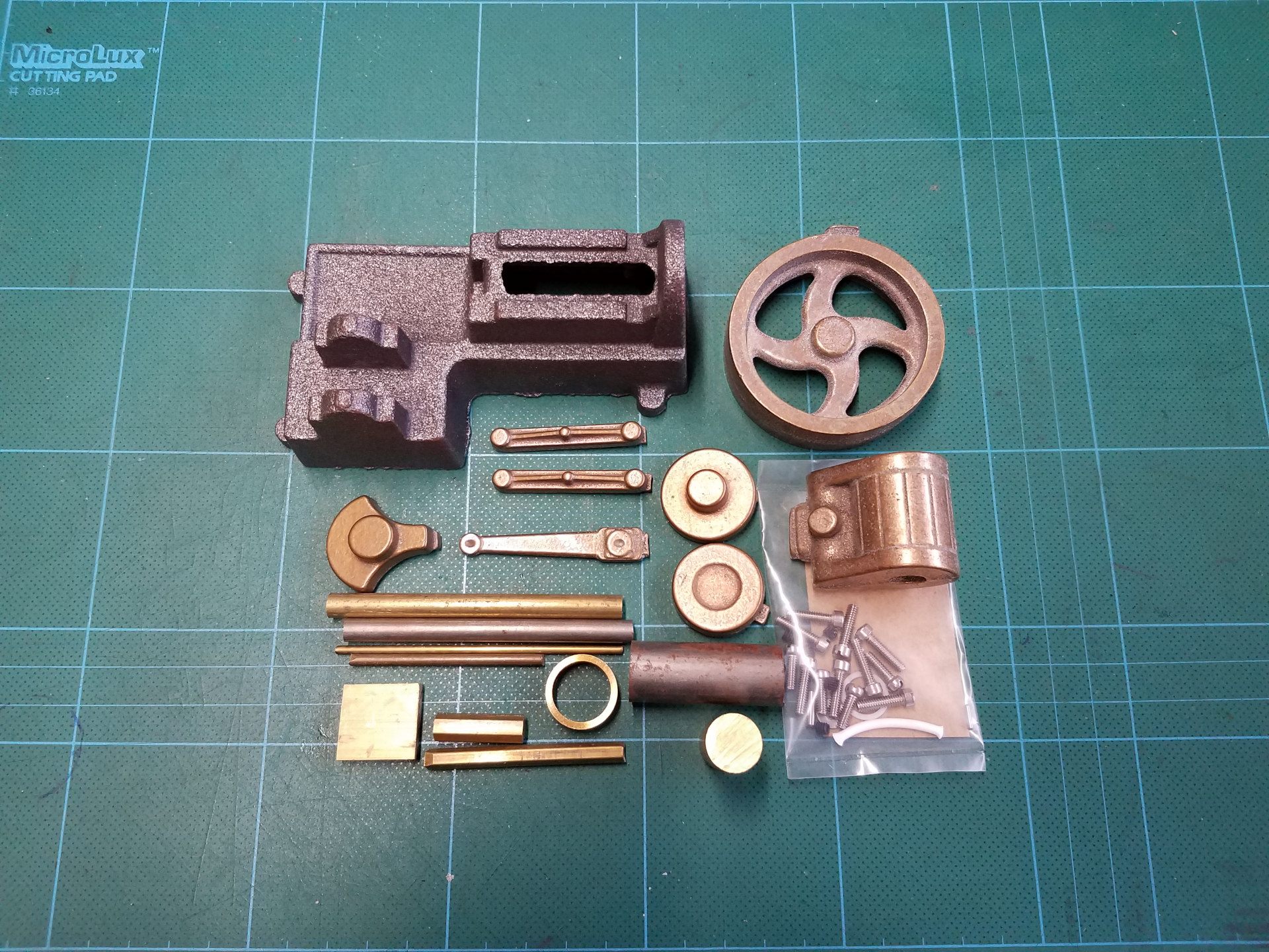
Here are the raw castings and components of the kit. The iron castings are the typical heavily textured sand castings from PM. The bronze castings are smooth and quite nice.
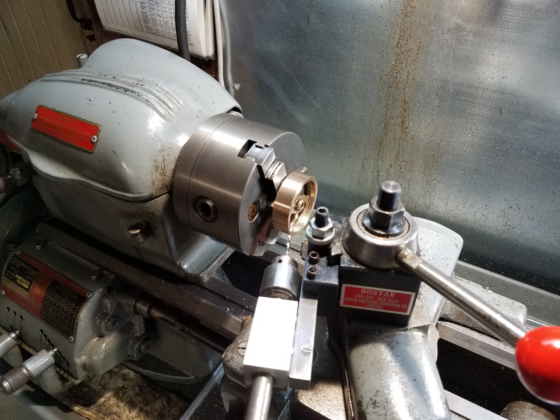
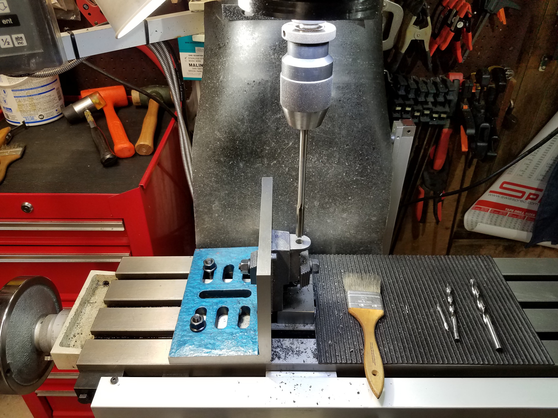
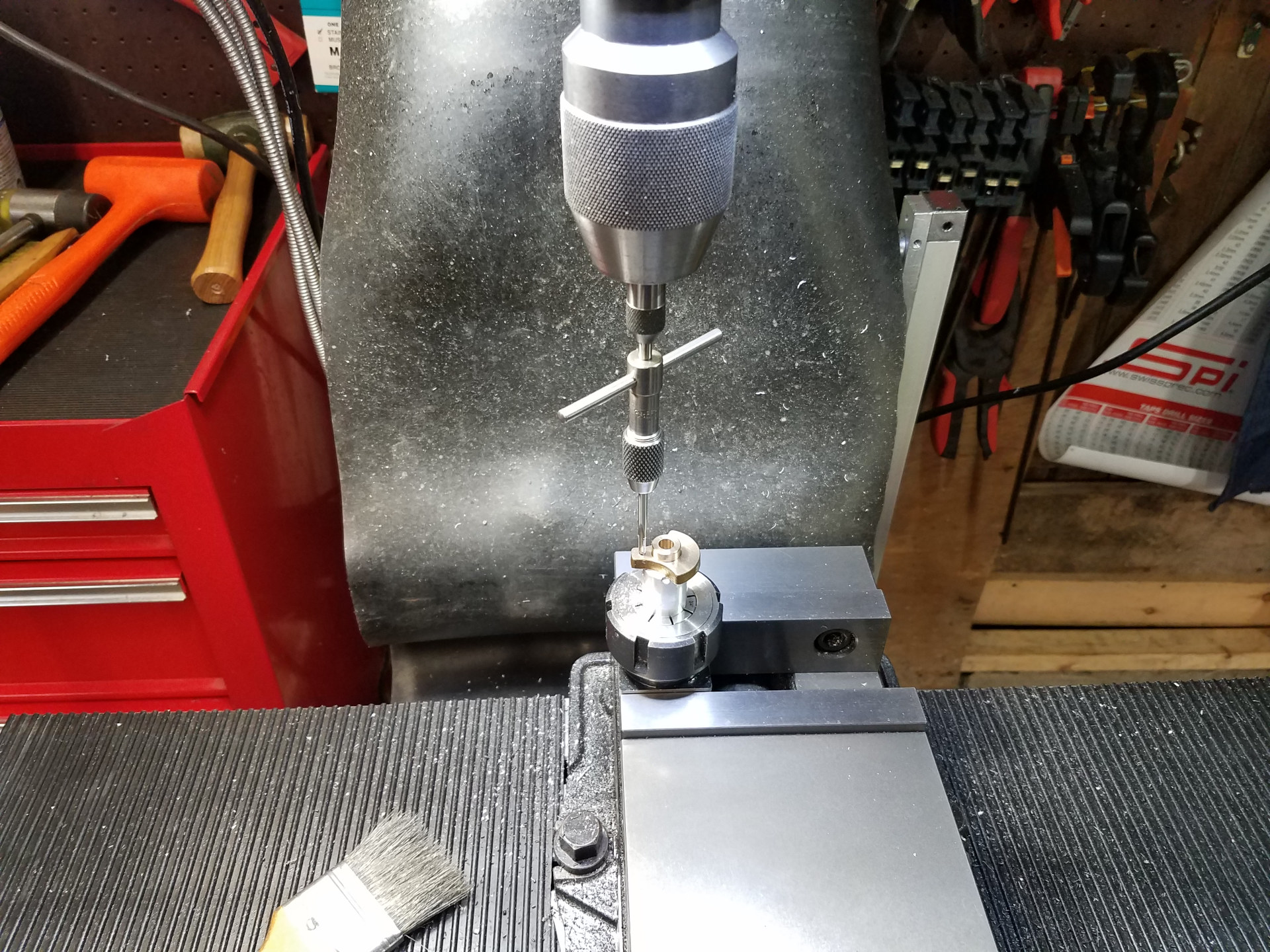
As usual for me, I started the build with machining the flywheel. The bronze machined quite well. Here I'm drilling the flywheel for the grub screw using the toolpost drilling jig. While most of the machining of the flywheel was done in the chuck, eventually it will be turned to final size on an arbor to assure concentricity.
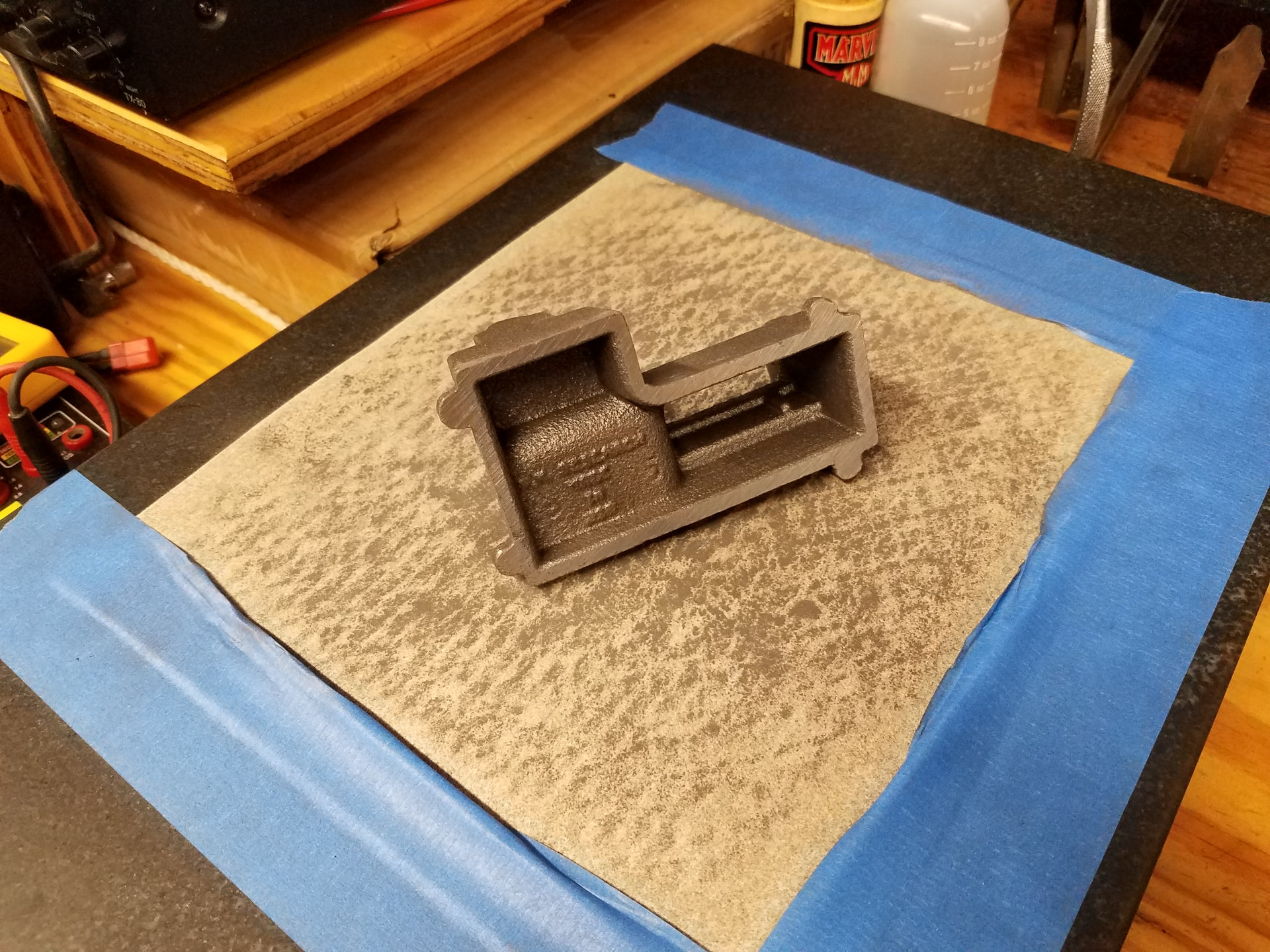
The bottom of the base was reasonably flat from the start. Some sanding on the surface plate finished it off nicely.
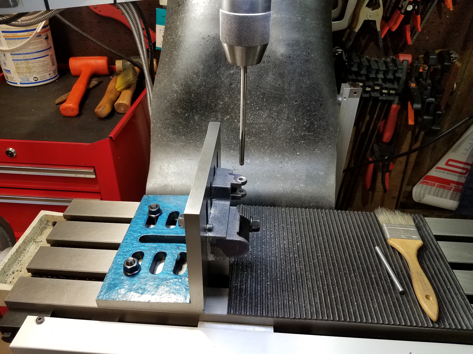
At the mill, the engine base was mounted onto an angle plate to begin the machining. After spotting the crankshaft bearing points with an end mill, here I'm opening them up after drilling with a reamer. The crankshaft bearing points are a very important datum point since many measurements are based off this point. It's very important to get them at the right spot.

Centering the mill's DRO from a piece of drill rod inserted into the crankshaft bearings.
Reaming the hole for the piston. The piston and the crank shaft need to be on the same plane and exactly perpendicular from each other or the engine will be doomed to bind and run poorly. This early work in the project is critical to a well-built engine.
The base is now mounted on the mini pallet for more work. A new feature of the mini pallet was adding drilled and reamed holes for 1/4" dowel pins for work alignment which proved quite handy during this engine build.
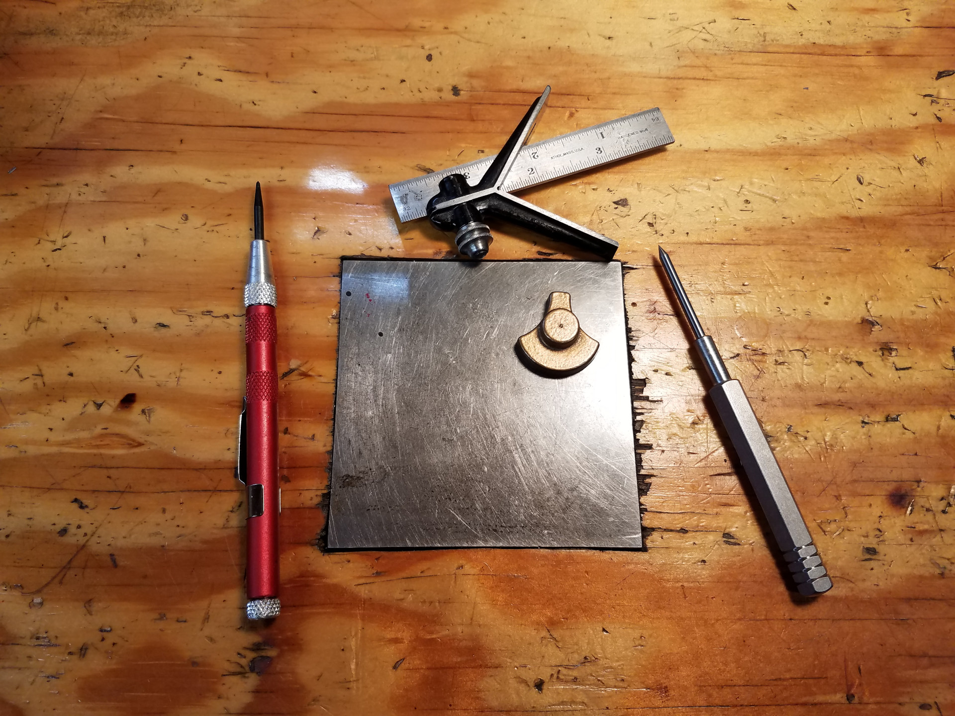
Getting started on the crank throw. The center of the crank throw was found with a center finder and punched.
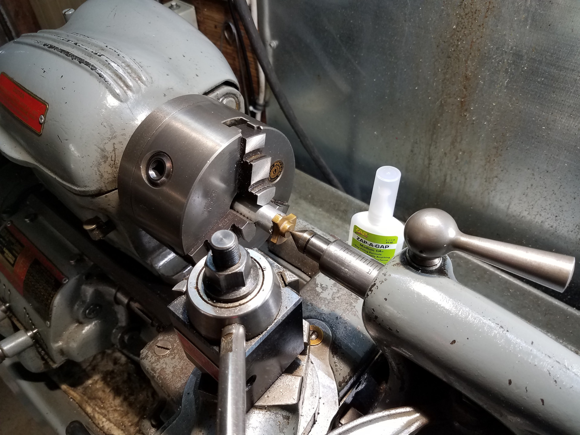
A dead center in the tail stock holds the crank throw against a faced-off aluminum round fixture while the CA cures. This technique for getting the work centered correctly on the fixture worked well.
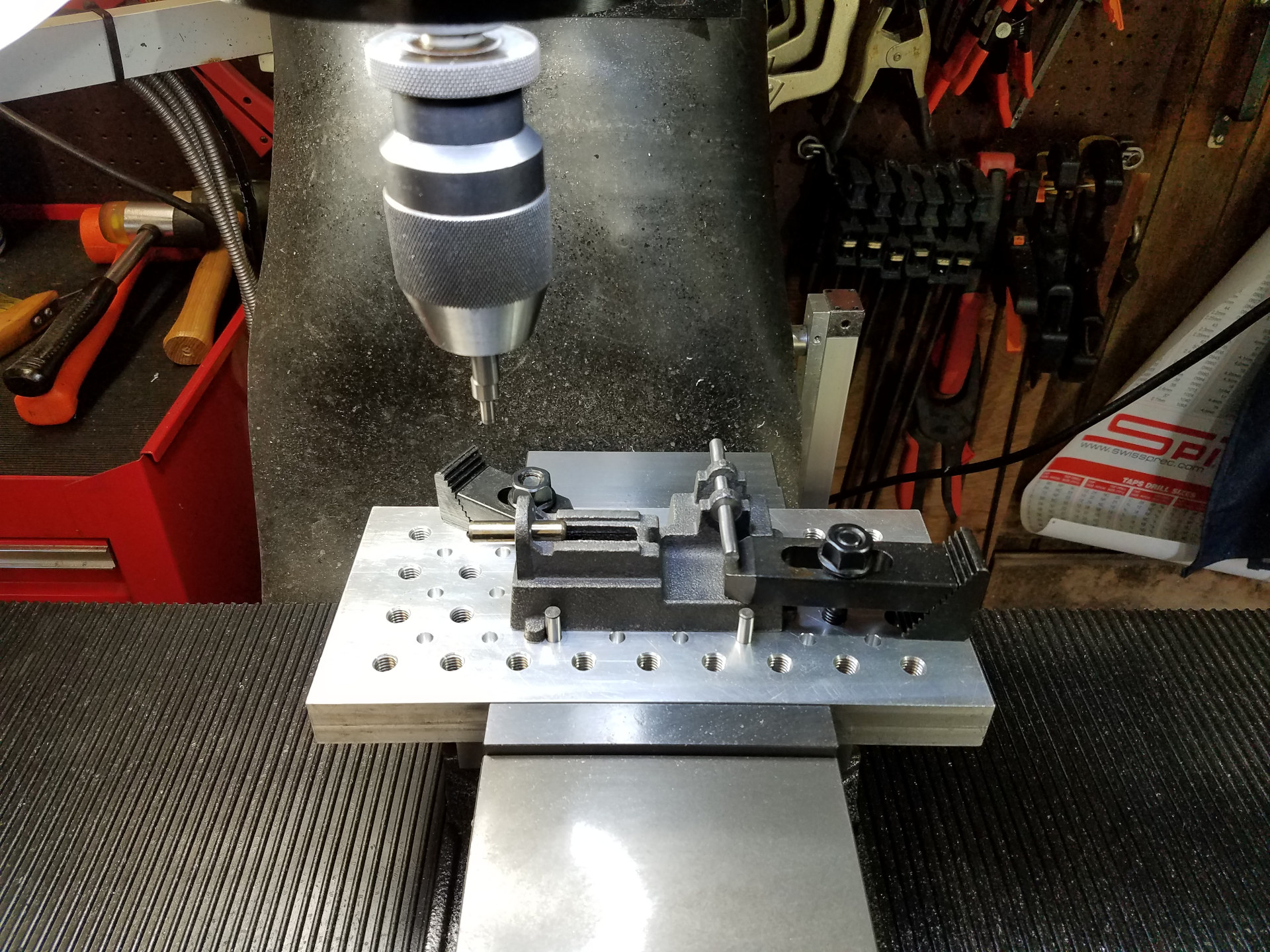
After the turning in the lathe was done, the same fixture was held in a ER32 collet block in the mill vise for drilling and tapping the throw.
The PM Research #3 engine build will continue with the next article.