The X axis DRO scale would prove to be the most challenging part of this DRO installation as I wanted to ensure I didn't lose any of the mill's Y axis movement. This meant the scale would have to be installed at the front of the mill table. For extra difficulty, I also wanted to have adjustable X axis hard stops and working power feed limits. All these features would have to fit in a relatively small amount of space.
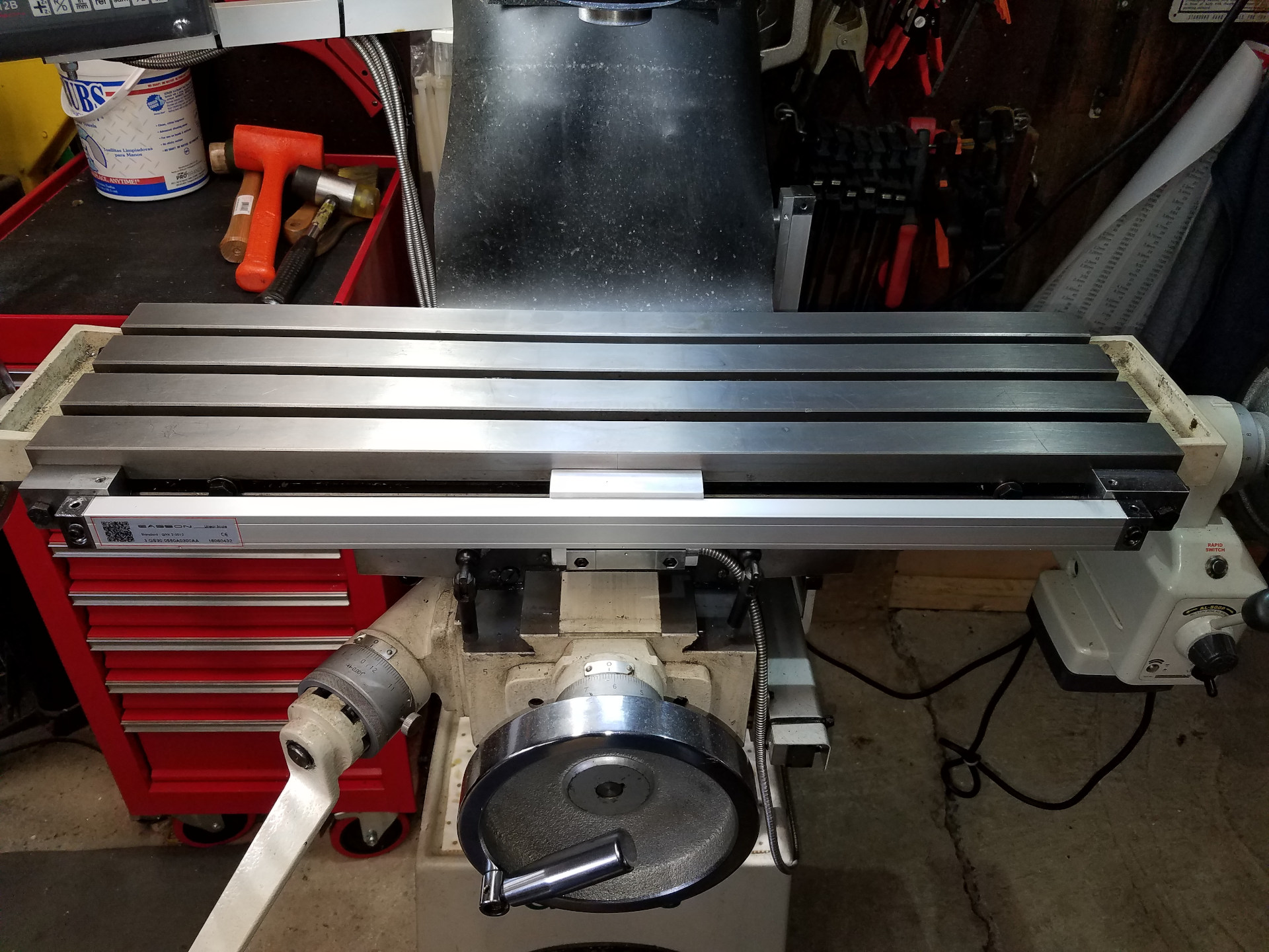
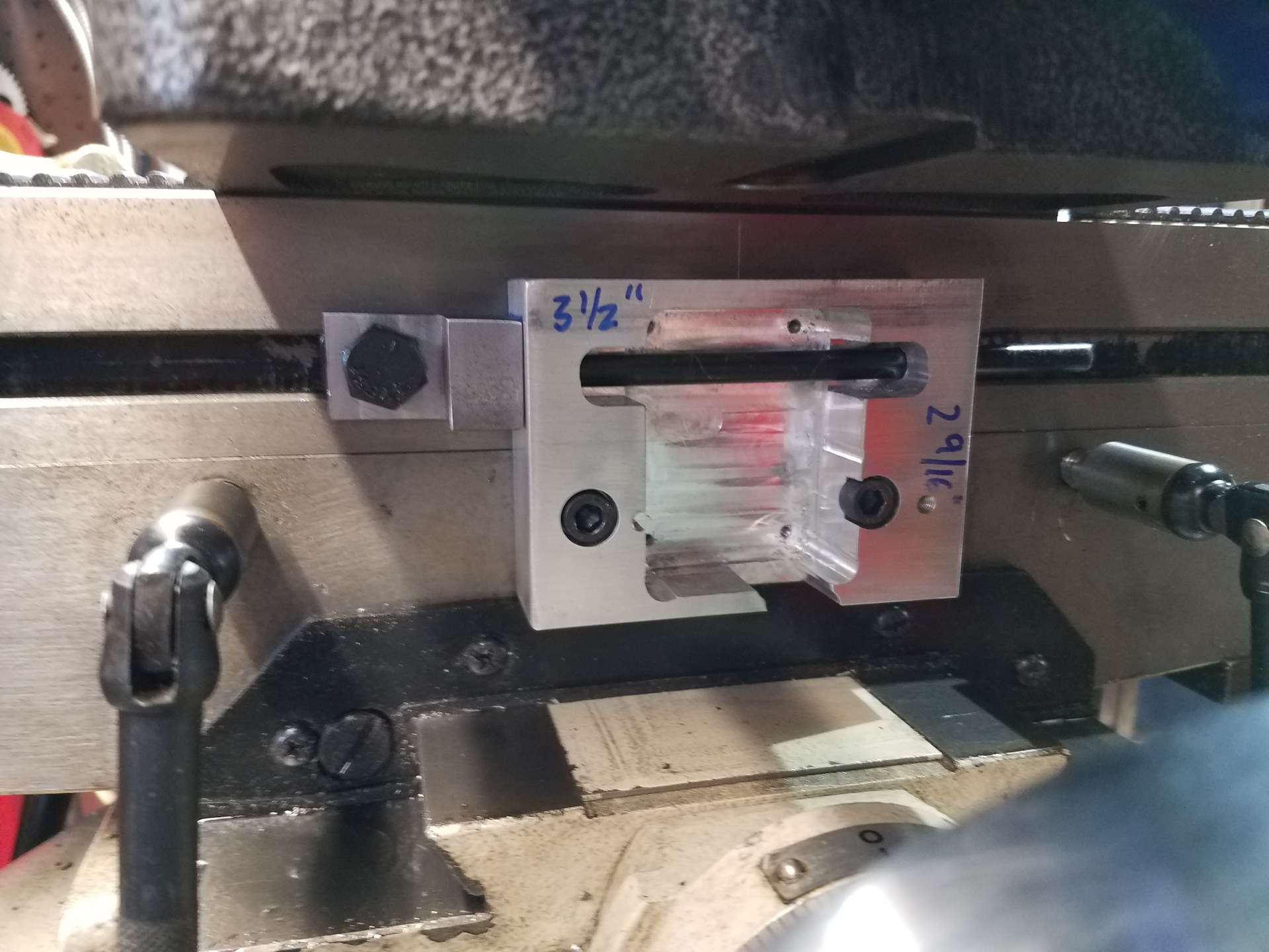
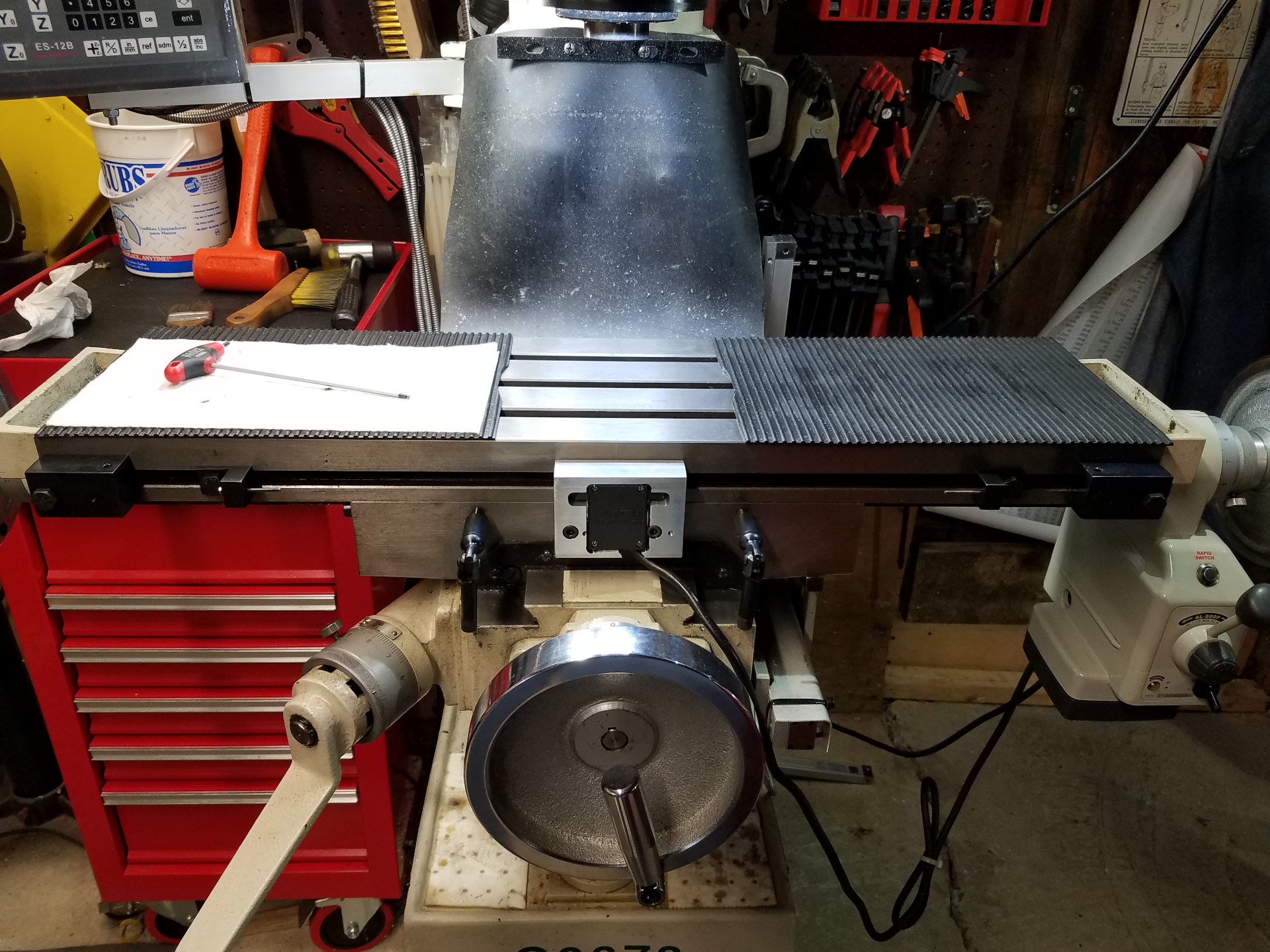
Due to the complexity of the X axis scale install, it was constructed in several stages so the mill wasn't down for weeks while parts were designed and manufactured. This picture shows the beginning of the last stage of construction which will add the hard stops and power feed limit functionality. With the scale's protective cover removed, you can see the mounting blocks for the scale mounted via the table's front T-Slot and the scale reader head mounting block in the middle of the table.
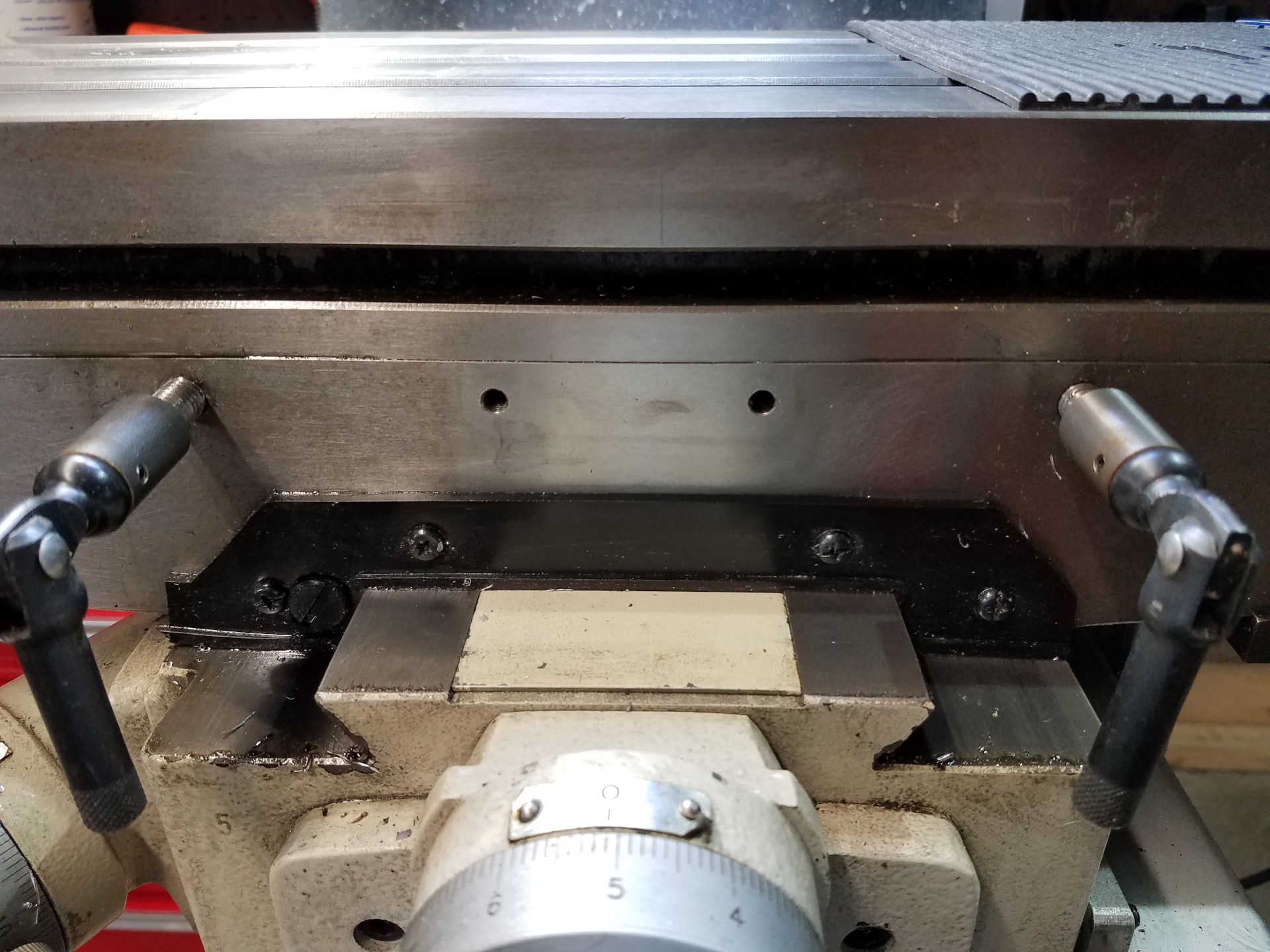
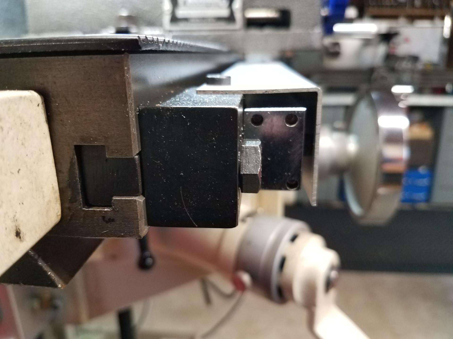
This is a close-up shot of where the scale reader head mounting block will be installed. The two tapped holes are from the original factory hard stop mounting. Also note that the factory gib lock handles from the Y and Z axis were reused and modified to work with the X axis gib. The Y and Z axis gib handles were replaced with aftermarket handles as described in the earlier article Grizzly G0678 Knee Mill Knob Jobs.
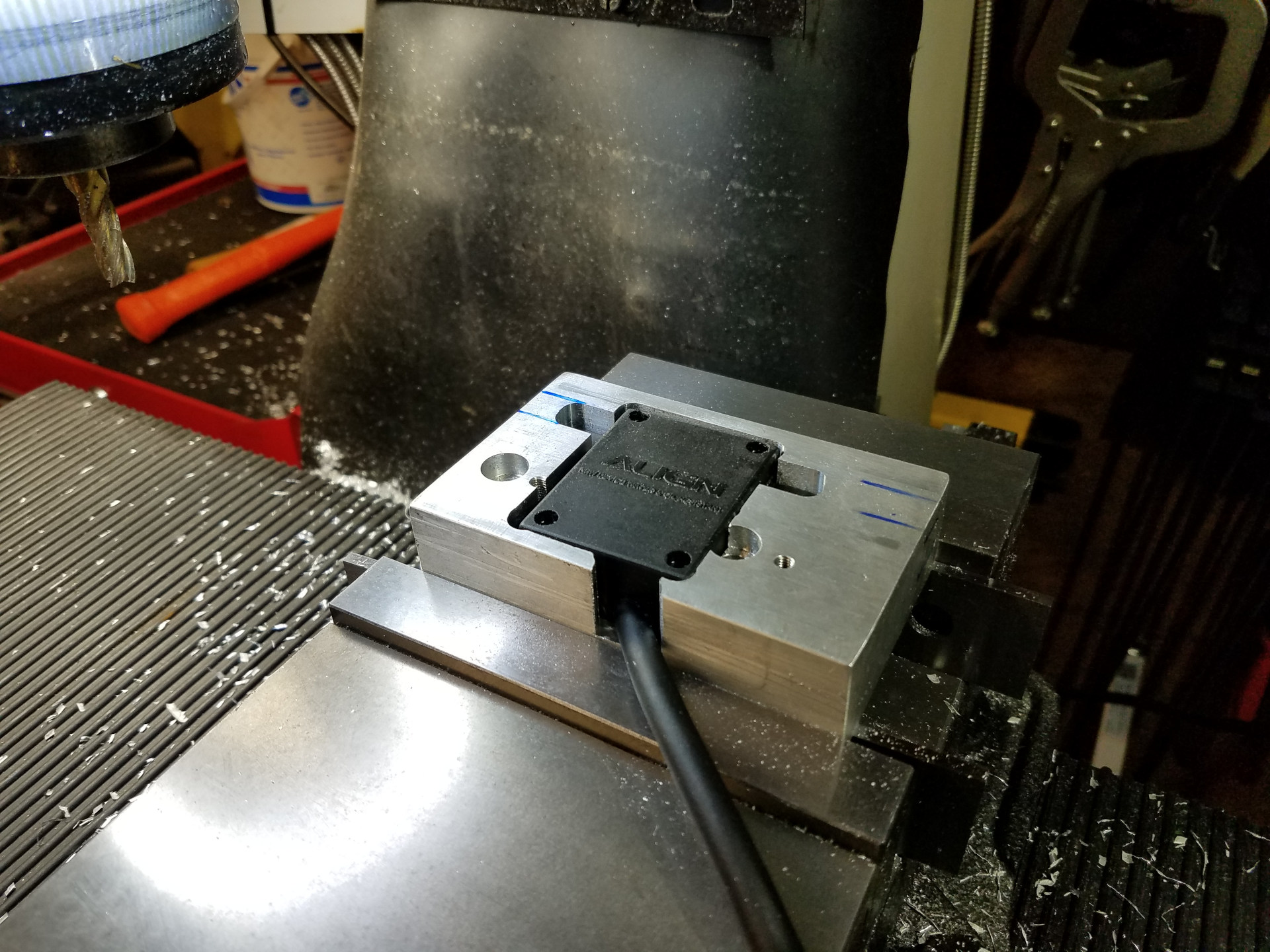
A cavity in the 1" thick scale reader head mounting block was milled to accept the power feed limit switch. The X axis scale reader head will eventually mount on this block, over the feed limit switch. Note: The prototype reader head mounting block shown here is aluminum while the final version will be steel.
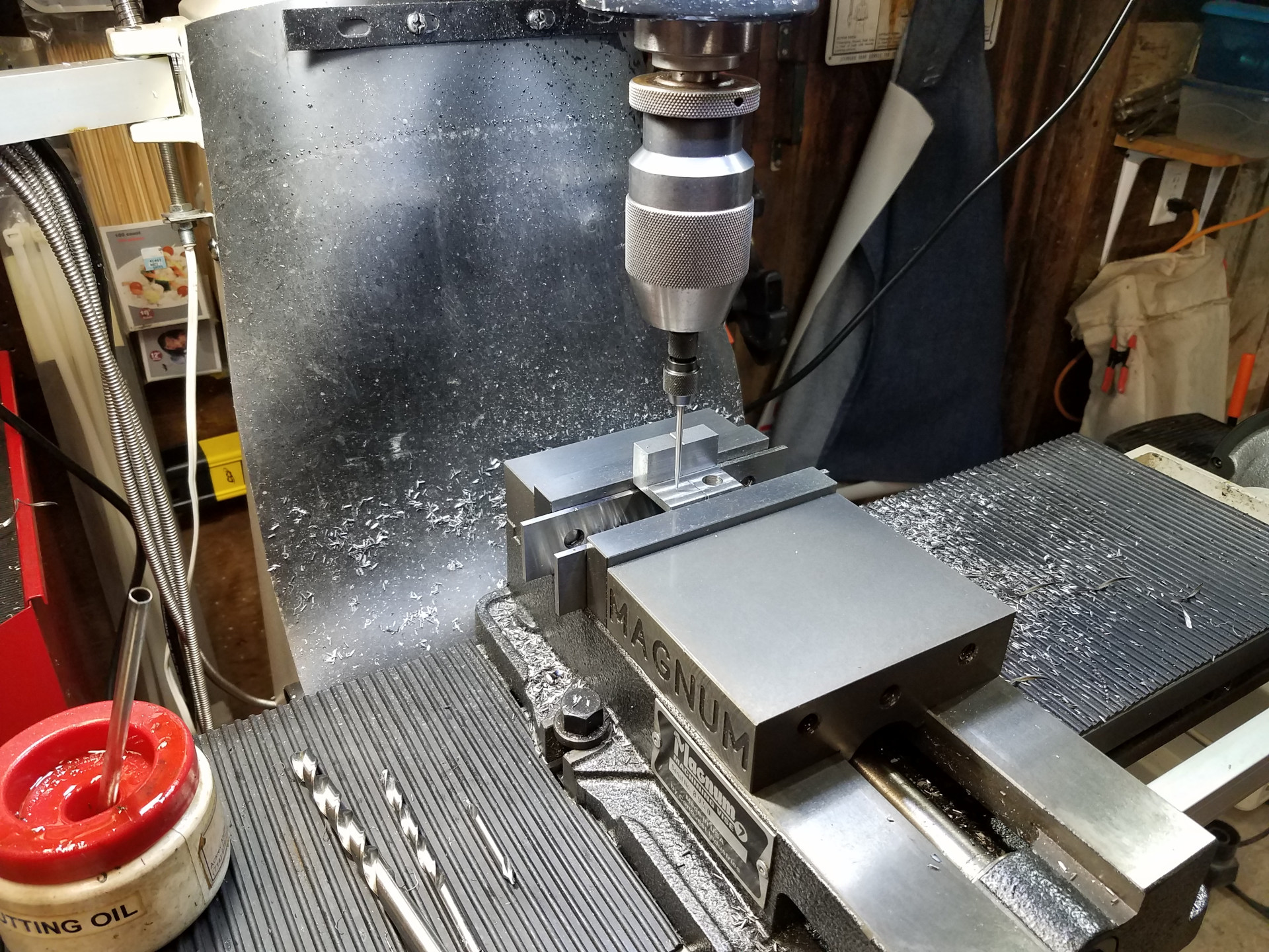
Started working on the adjustable feed limit stops that will mount at the T slot in front of the table.
The reader head mounting block is now attached to the mill using the factory tapped holes. One of the feed limit stops is marked with a transfer punch for the location of the 4-40 cap screw (stop pin) that will activate the power feed limit switch.
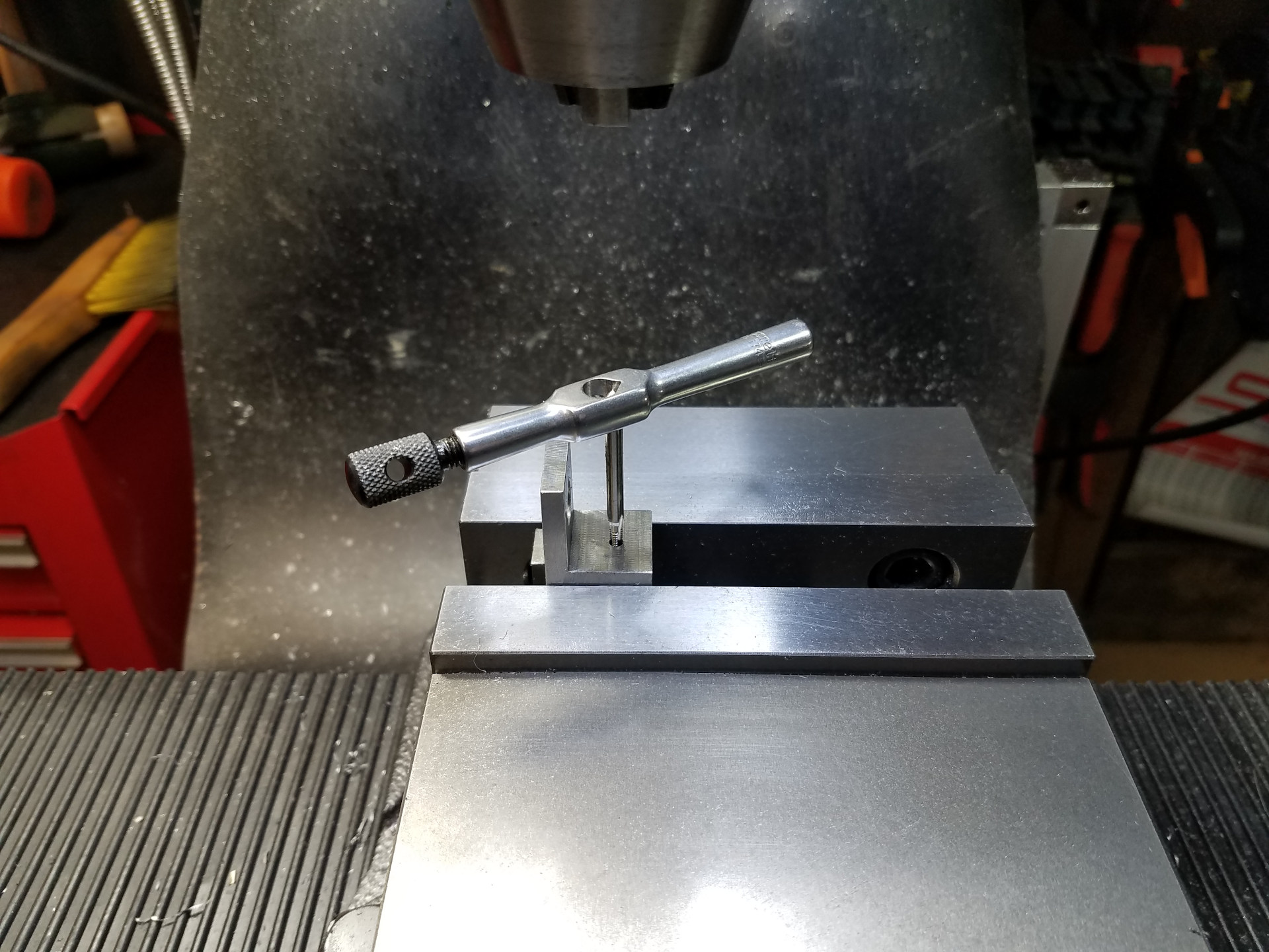
The bolt hole location found in the previous operation is tapped 4-40.
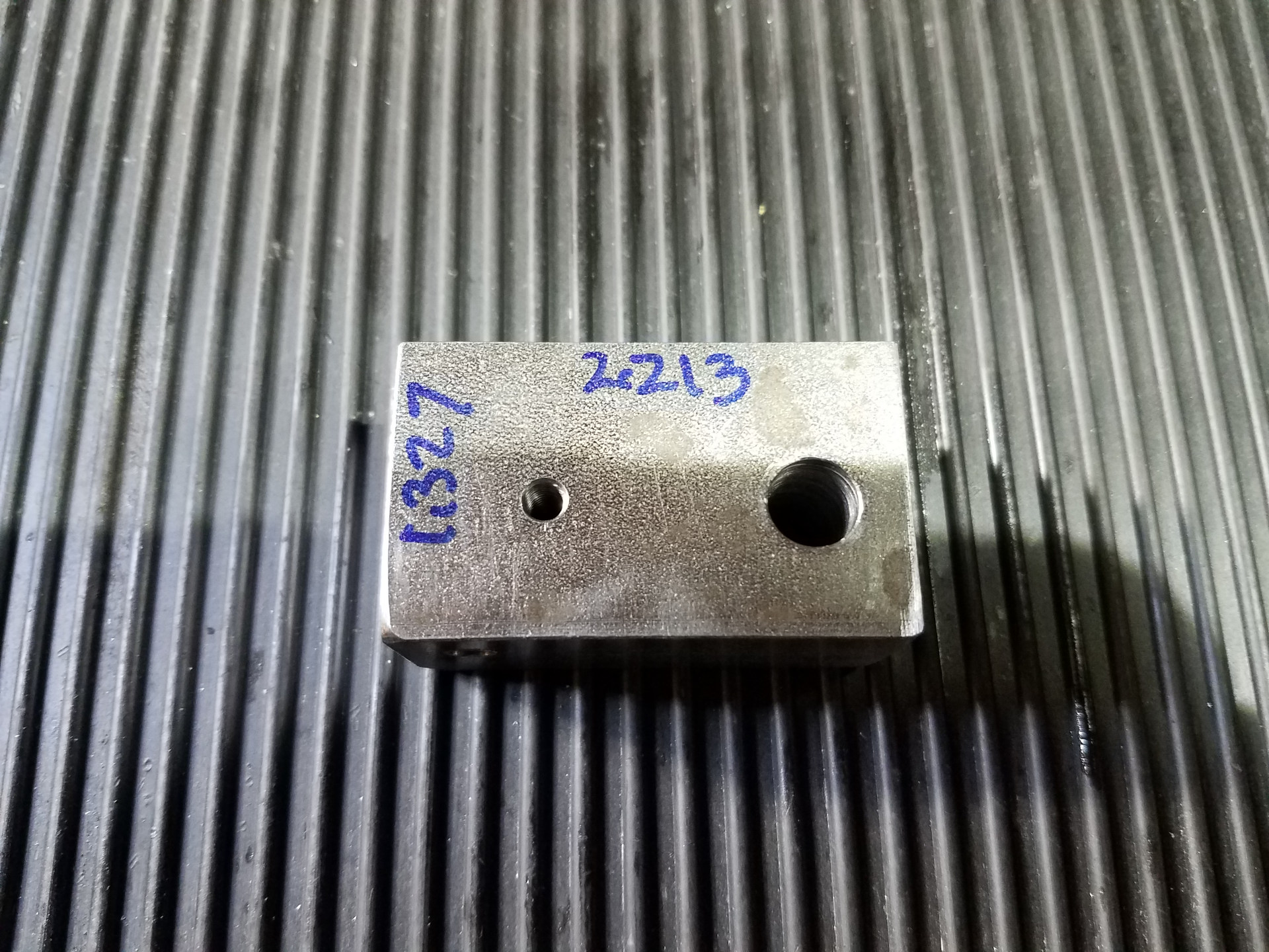
This is one of the 1" thick scale mounting blocks. It's fastened to the table via the front T-Slot. Four custom T nuts that precisely fit the oddly sized T-Slot in the front of the mill table were made at an earlier date.
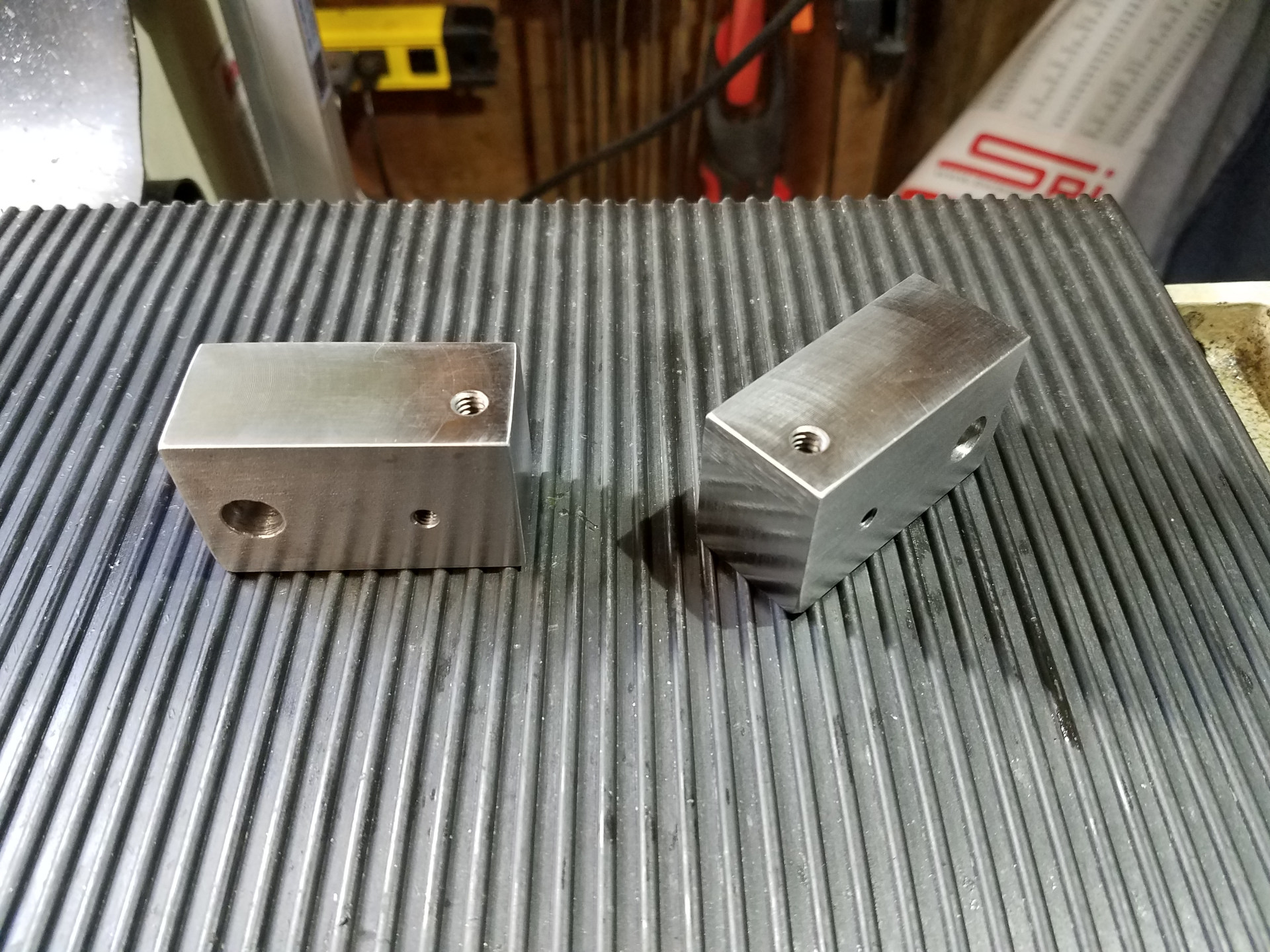
Shot of both the left and right hand blocks. The large hole is a clearance hole for the T-Slot mounting bolt. The other hole on the same face is the threaded for mounting the x axis scale. The threaded hole on the top if for mounting the protective cover.
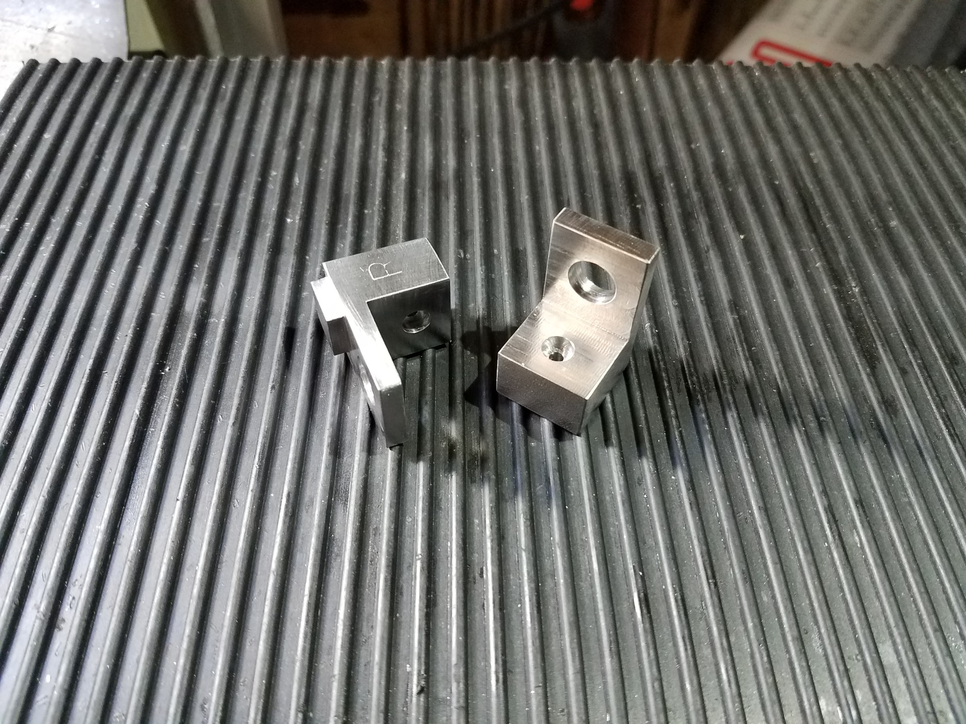
Detail shots of the completed adjustable stops. Note they are keyed to fit inside the T-Slot, so they don't twist in a circle when you tighten the mounting bolt. The small threaded hole is for the 4-40 stop pin, the other is a clearance hole for the bolt for the T-Slot nut.
What it looks like with all the power feed and stop hardware attached before the scale is mounted.
A video showing the action of the power feed and hard stops.
Once the feed limit switch is tripped via the stop pin, you can turn the wheel an additional amount so that the adjustable stop hits the scale reader head mounting block which is the hard stop. The point of the hard stop is repeatability, with it you can stop at the same numbers within the limits of the DRO scale (.0002"). Just using the power feed limit switch will not provide this amount of accuracy.
Even at rapid traverse speed the stop pins won't crash the feed limit switch. The stop pins are 4-40 caps screws which can easily be fine-tuned on how far the screw will enter the reader head mounting block to activate the feed limit switch. On my machine, when the switch is half-depressed it will kill the power feed. You can push-in the switch flush with the case (full depressed) without damage so you want to adjust the cap screws (stop pins) so that when you hit the hard stop the button is not beyond flush.
By loosening a bolt, the adjustable feed limit stops can be moved along the front T-Slot where needed, although normally they are parked at the ends of the table movement to stop the power feed.
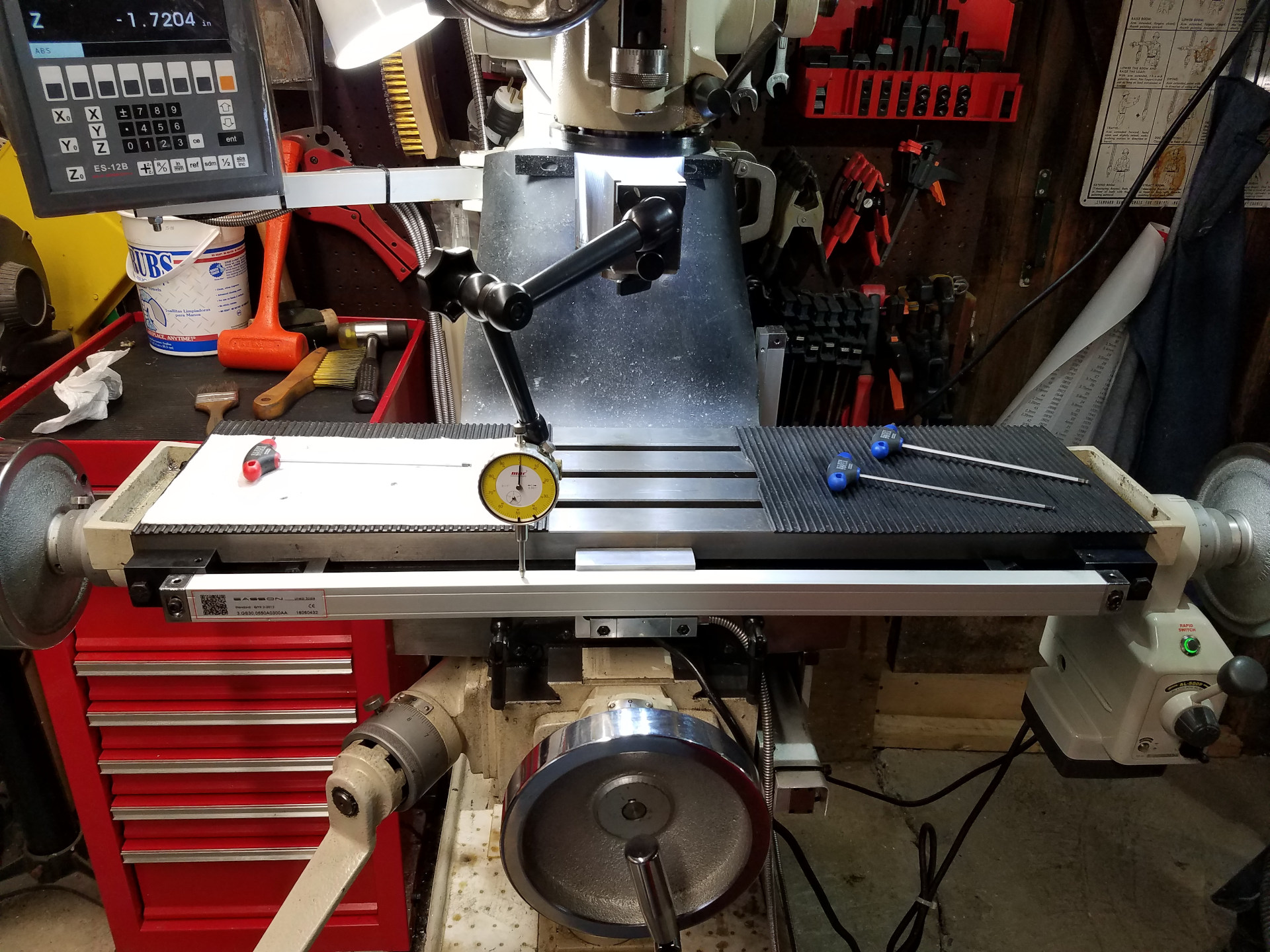
With all the hard work of the power feed installation completed, it's now time to mount the X axis scales. Like the other scales, this scale needs to be zeroed-in with a dial indicator. The scale reader head is mounted slightly to the right of the table travel center for bolt clearance. Since I bought a generously sized scale that is comfortably longer than the table travel this doesn't present a problem.
Here the scale protective cover has been attached to the scale mounting blocks. Notice the cover rests against the mounting block and the cap head screws that mount the scale, not against the scale itself.
There was also a limit on how far the X axis scale can project from the front of the table as the dividing plates for my rotary table extend below the table top at the front. When rotary table mounted, there is a 1/4" clearance between the scale cover and the back of the dividing plates.
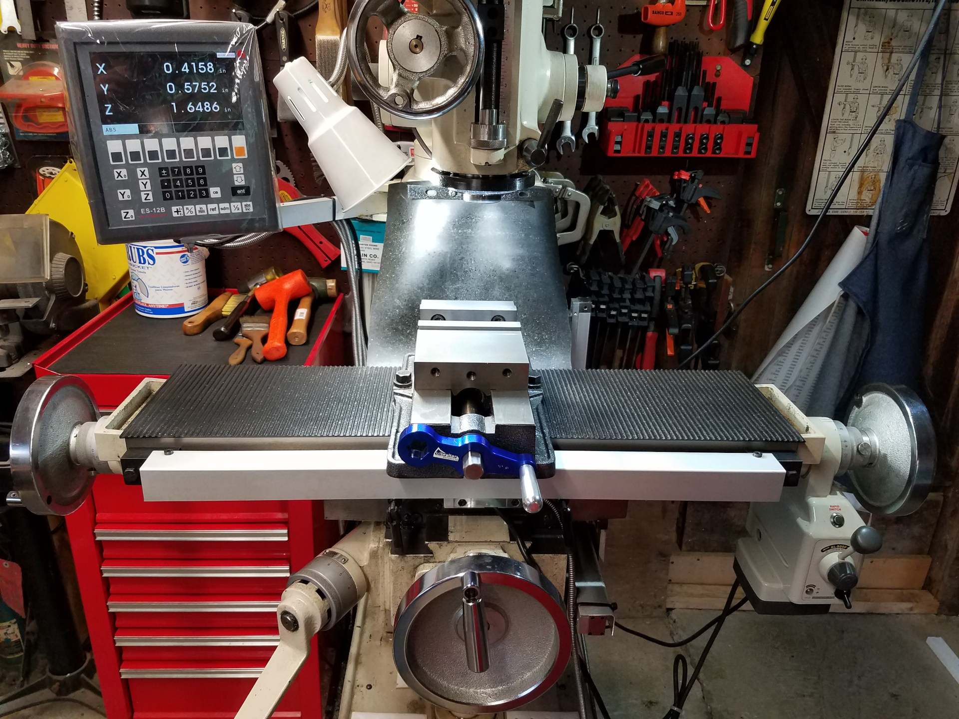
The completed DRO installation.
While it was a bit more work than the standard "slap it together" weekend DRO install, I'm happy with how it all came together in the end. The mill still has working hard stops in both the X and Y axis that actually work better than the factory design. Also the power feed limit switches are functional and integral to the hard stops so you don't have to worry about crashing the power feed against a stop and stripping it's internal brass gear. The scale mounting hardware is very sturdy which helps give a stable and repeatable measurement.
The entire DRO system has been completely trouble-free since installation and works well.