A variable speed drive is a nice option for any piece of metal shop equipment. For the lathe, it's especially handy to be able to adjust the spindle speed during a cutting operation, like increasing the RPM's during a facing operation so the cutting speed at the tool is constant as the cut diameter gets smaller. In the next few articles I will describe how I installed a variable frequency drive into my old South Bend 10K lathe.
Before we get into the VFD installation, let's review how the speeds are changed on a stock SB 10K lathe.

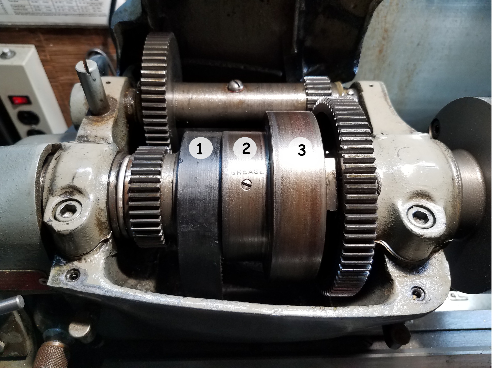
Amazingly South Bend was still using flat belt technology in 1972 when this lathe was manufactured. To change the speed of the lathe, the belt is moved to position 1, 2 or 3 on the cone pulley with position 1 being the fastest speed while 3 is the lowest.
The operator can enable a 5:1 speed reduction by engaging the back gears. This is done by pulling out the bull gear lock plunger visible at the right of the bull gear and then using the back gear lever at the left to engage the gears.

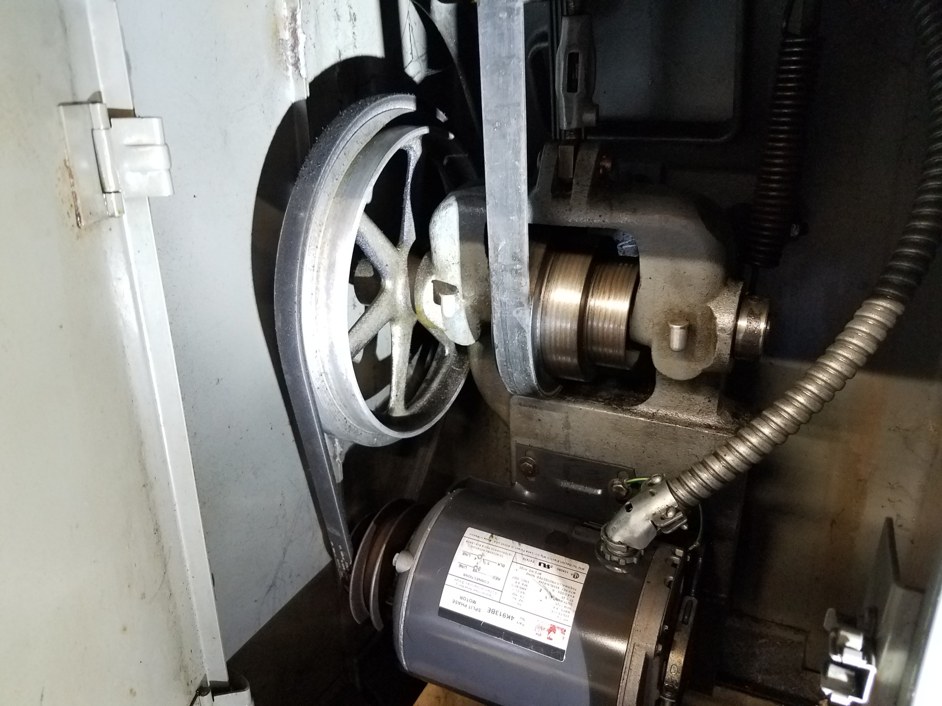
Down in the motor cabinet, the operator can select high or low speed by moving the belt connected to the motor. Here the lathe is in the low speed range. To change speeds, the belt is simply pulled or rolled off the flat pulley at the top, engaged into the other position at the motor sheave and then rolled onto the correct spot on the flat pulley. It's an ingenious setup that allows the operator to change the belt position without loosening the motor and I've never had the motor belt slip. The downside is that you have to get down at the floor on one knee to access the belt in this under motor drive (UMD) lathe.
So you have 3 speeds at the cone pulley of the spindle, a back gear option for all those speeds and then a high/low speed from the motor. So 3 times 2 times 2 gives you 12 lathe speeds.

This chart from South Bend's How to Run a Lathe summarizes the speed choices for this lathe. Right away you can see some issues. For one, SB doesn't recommend using the back gear drive in high speed, so three speed selections are gone. Also, there is a large gap between speeds 1 and 2 while using high speed. Additionally, since the operator has to get down on one knee to change from high to low speed, generally the lathe will stay on low speed. For some reason, different actual speeds were measured using a laser tachometer compared to the SB chart above and some of the measured speeds in high versus low range are very close to being the same.
Boiling it all down, instead of 12 lathe speeds you realistically get 7 speeds: 1370 in high, with 786, 474 and 286 in low and by using back gears, you get 151, 91 and 55. Quite a drop from 12 speeds!
Nevertheless, I ran the lathe for quite a few years just using those 7 speeds. One of the major advantages of the upcoming VFD installation will be unlocking the 1400-800 speed range which will be nice for the small model work that is done on this lathe.
When using the VFD, the lathe will always be run using the low speed position on the motor sheave and the motor will be run faster with the VFD than normal (over 1725 RPM) to reach the high spindle speeds. While I'm not interested in totally eliminating flat belt movement for speed control, by using the variable speed capability of the VFD belt movement will be greatly reduced. Belt Position 1 will offer the high lathe speeds from 1400-600, Belt Position 2 will provide the middle lathe speeds of 800-300 while Belt Position 3 will offer the low speed range 400-150 or lower. Back gears will still be available for really low speeds. The idea is to not run the lathe using very low motor speeds to avoid motor armature overheating and also stay away from very high motor speeds so the lathe's drive unit isn't over-spun. Remember, this lathe uses plain bearings everywhere so it's better to keep the RPM's at a sane level.
Next article will go over the motor and VFD selection.