Presented for your reading pleasure is a small series of articles documenting my build of Elmer Verburg's Geared Engine, often called Elmer's Engine #5, the name of which is derived from the chapter number of the compilation book which describes this engine and many other projects. The cycloidal gearing of this engine makes it a fairly unique project and interesting to watch while running. This engine was not built from a kit and is mostly comprised of bar stock.
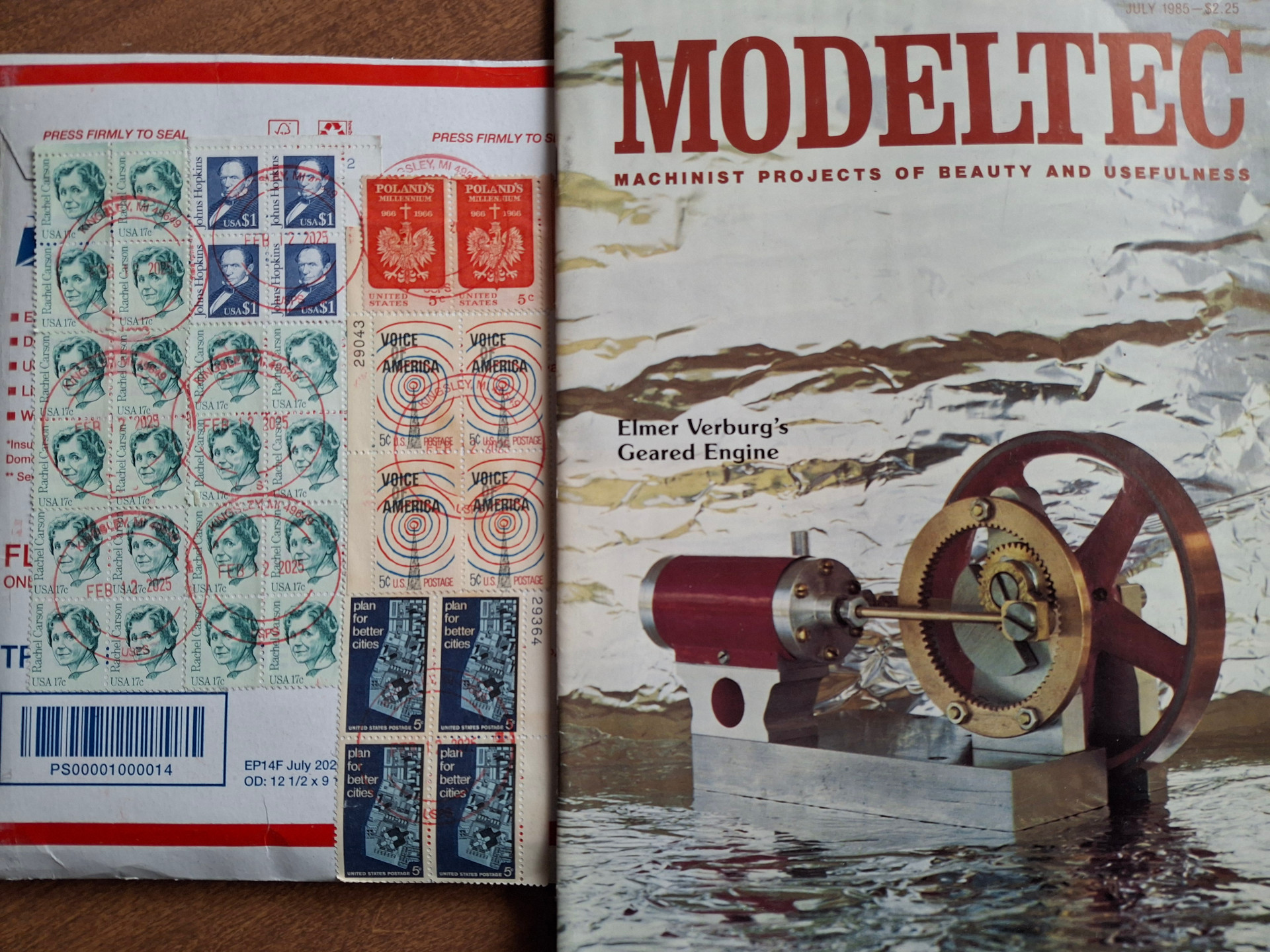
Elmer Verburg was a prolific writer and builder of model engines in the eighties. Many of his projects were published in the now defunct Modeltec magazine and those designs were later combined into a book called Elmer's Engines. Unfortunately not many of copies of that book were published and it tends to be expensive on the used market but if you look around you can find electronic scans floating around the net.
Two articles in the web forum Model Engine Maker were very helpful to me for this build and any part not covered here should be shown in one of these:
https://www.modelenginemaker.com/index.php/topic,4087.0.html
by arnoldb as a general build article and
https://www.modelenginemaker.com/index.php/topic,840.0.html
by Inky Engines as I like the look of his version.
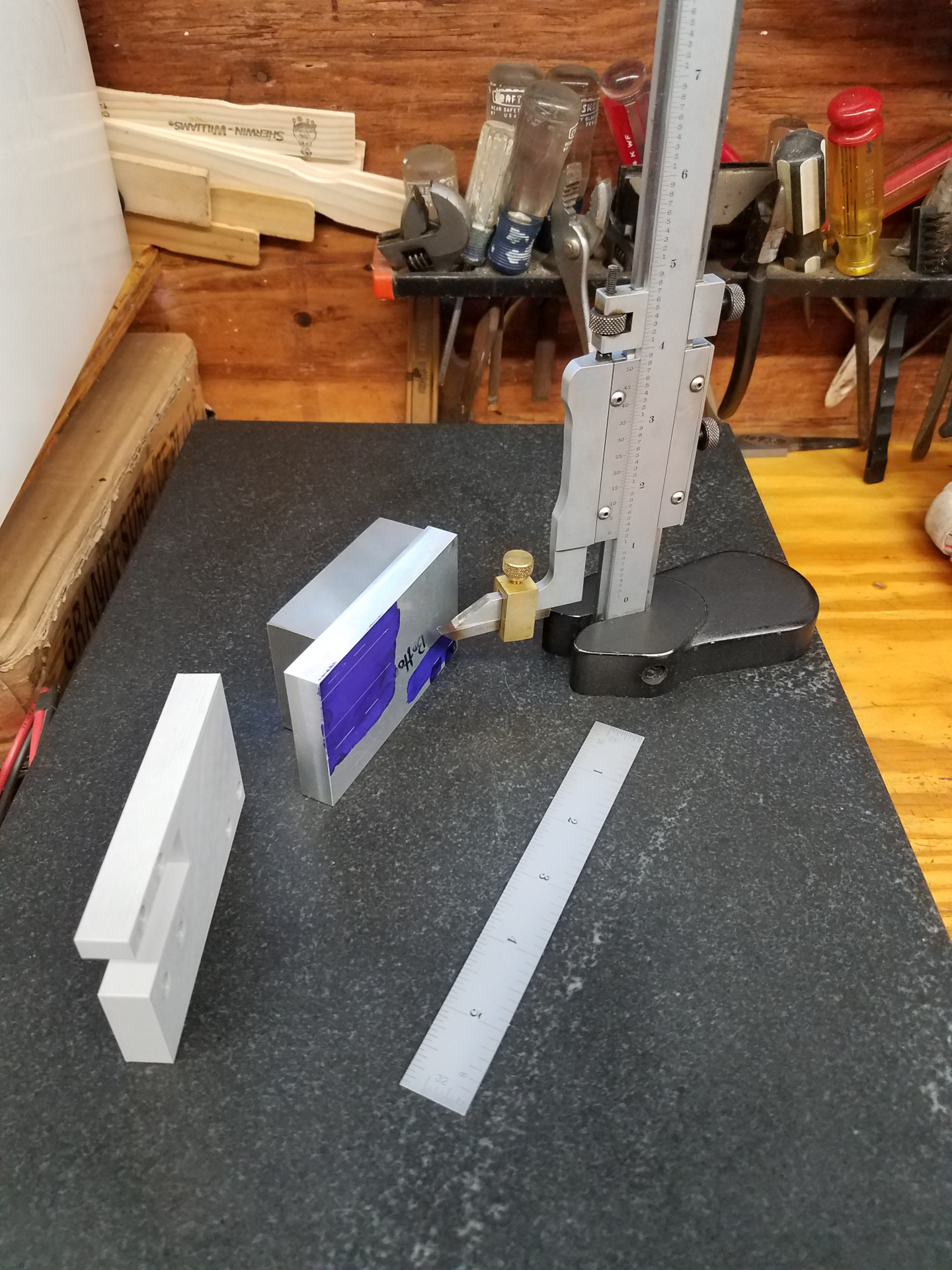
Like most projects, this one starts on the surface plate with the old Starrett vernier height gauge. While these are just reference lines as the DRO on the mill will be used for actually spotting the holes, I tend to practice what I call "defensive machining" as my erratic shop time and small brain make it really easy for me to make bone-headed mistakes. Belts and suspenders for me. In that thinking, to the left of the base is also a 3D printed one for reference as this is the first model that I completely modeled in CAD.
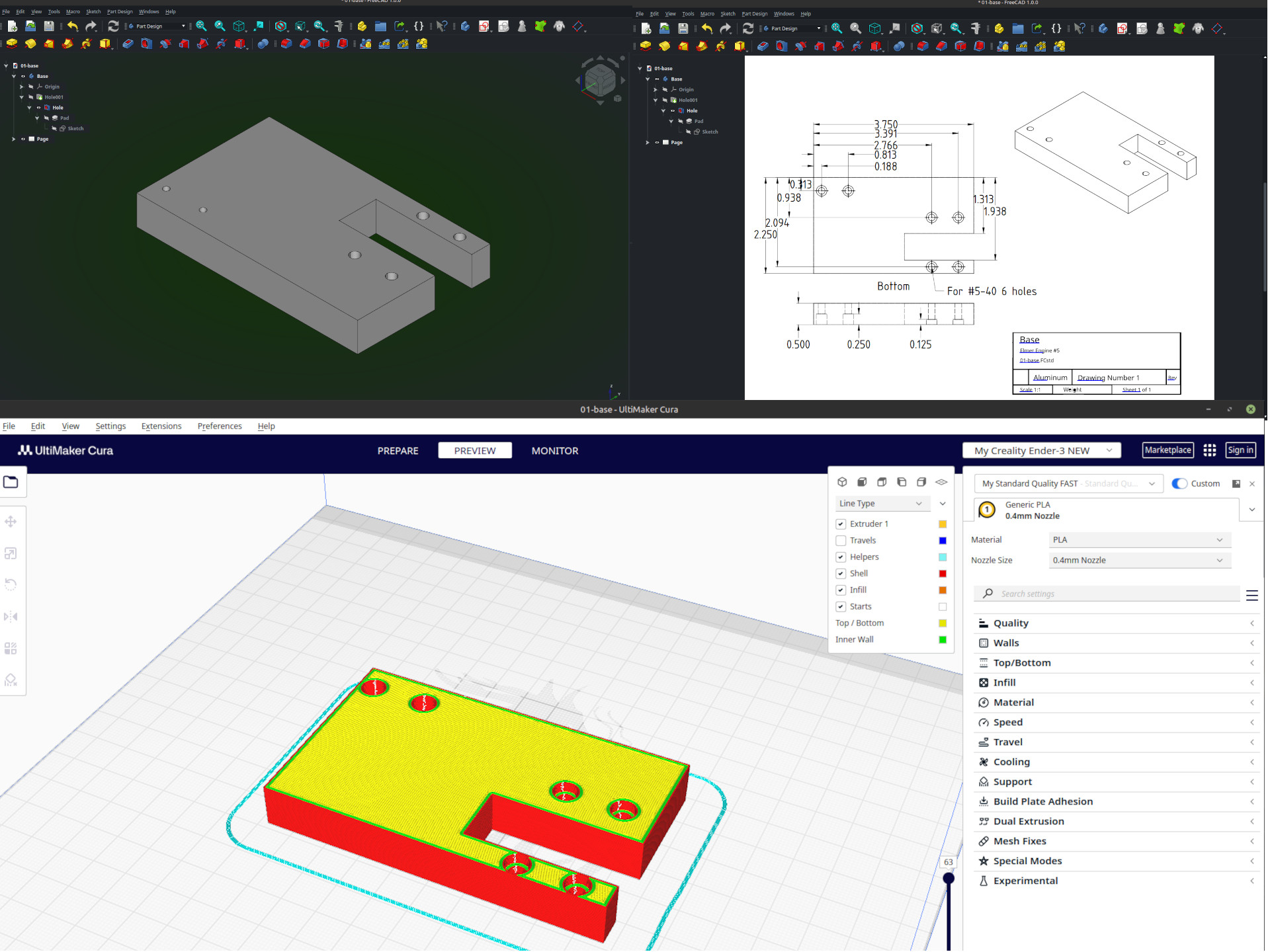
With the parts modeled, it was easy to make shop plans that are easier for me to read than Elmer's and of course 3D print a part. It's also possible to use a CNC mill for the machining as well but I'm not there yet.
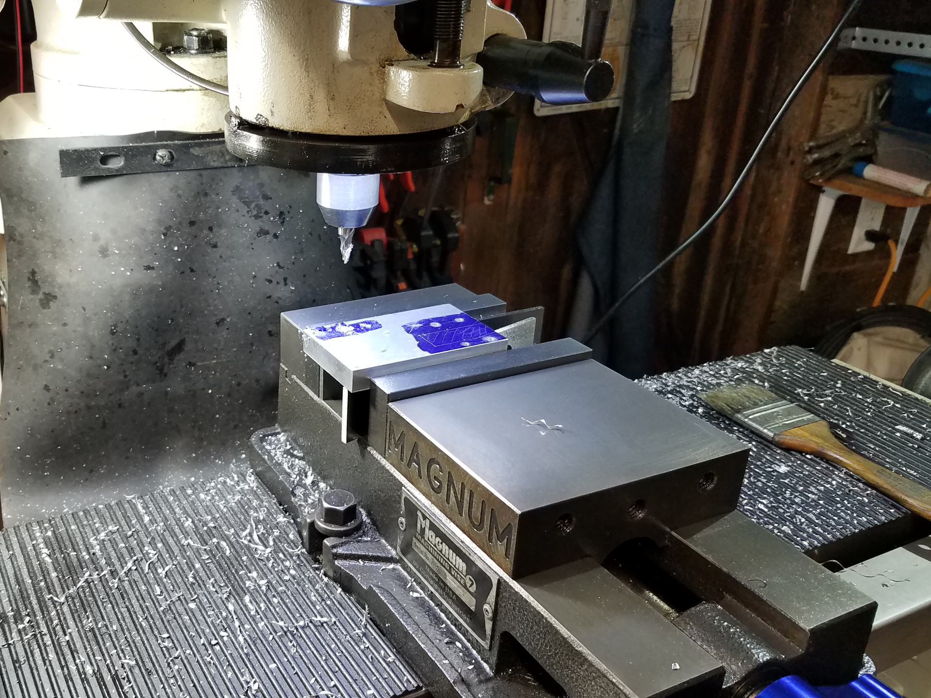
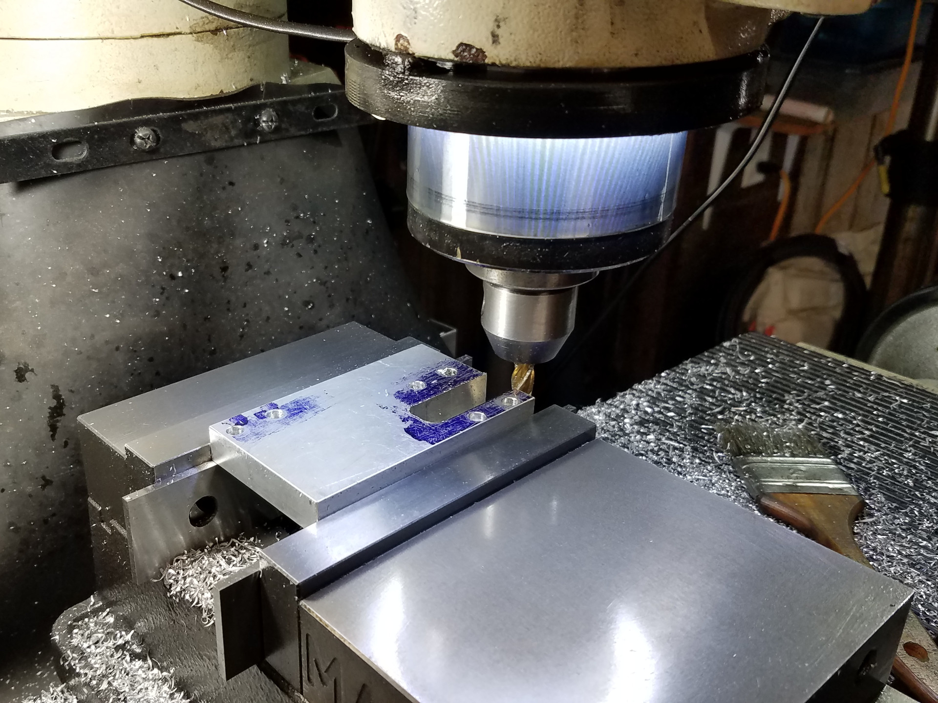
Using an end mill for counter-boring the base for the socket head screws. The 3D printed part makes it easy to verify I'm actually counter-boring the correct side and not the opposite, not like that has ever happened before. Nope, never did that.
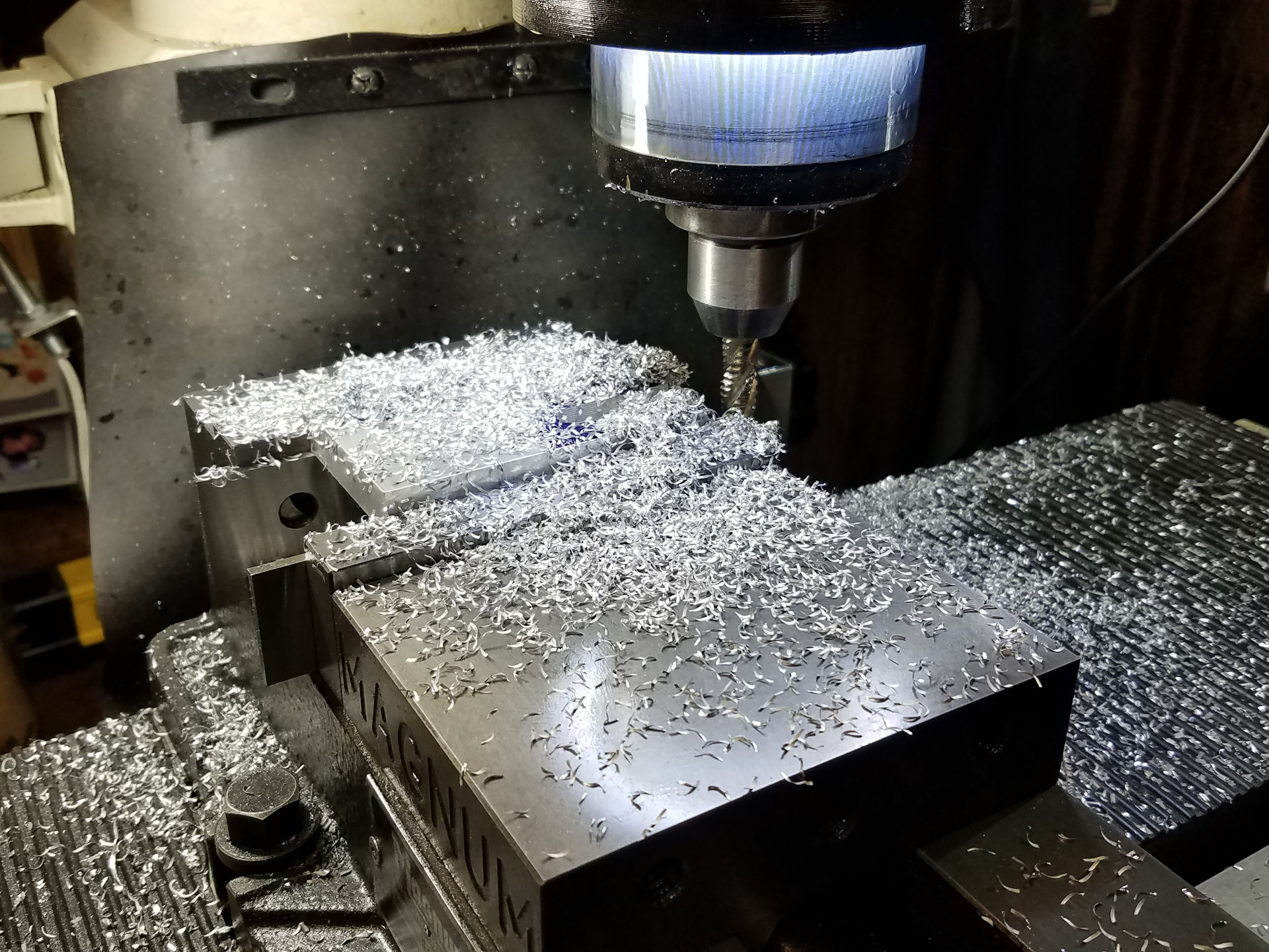
Using a roughing (or corn cob) end mill for maximum mess to clear the hole for the flywheel in one pass.
And then cleaning-up with a traditional end mill.
Using a flycutter to clean-up the top of the base. I'm using one of those small, round carbide cutters (RCMT0602) which work great for this type of work. Later on, I found a RCGT0602 version is also available which is sharper for non-furious metals like aluminum. Kurtis with CEE on Youtube uses this type of round carbide insert often for his much larger work but I've also found the round shape to be very useful in the hobby shop.
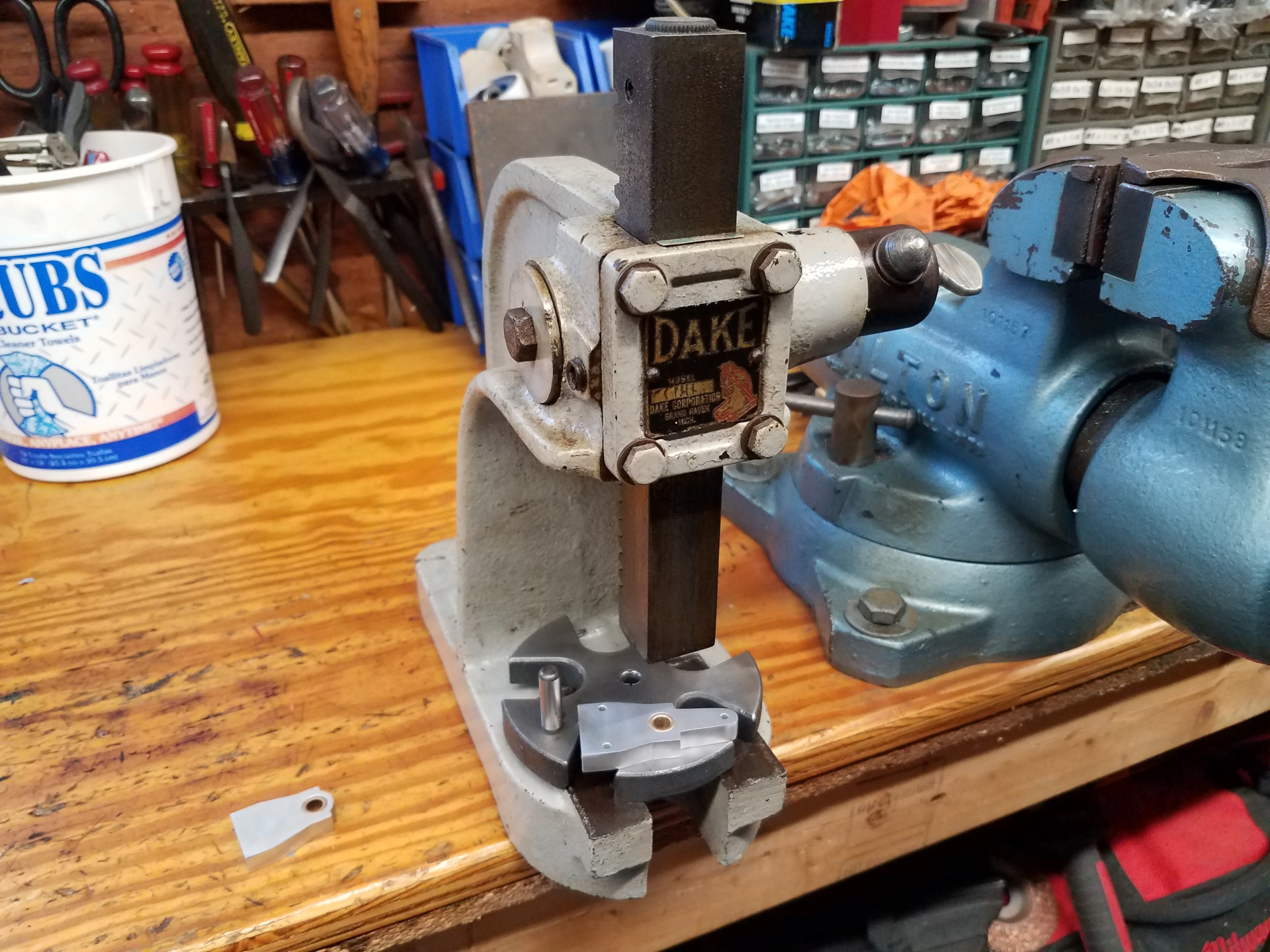
Here I'm using the lil Dake to press oilite bearings into the bearing holders. The important holes were spotted using the DRO on the mill, while the cosmetic outer features were milled to a line and then finished with a file or belt sander.
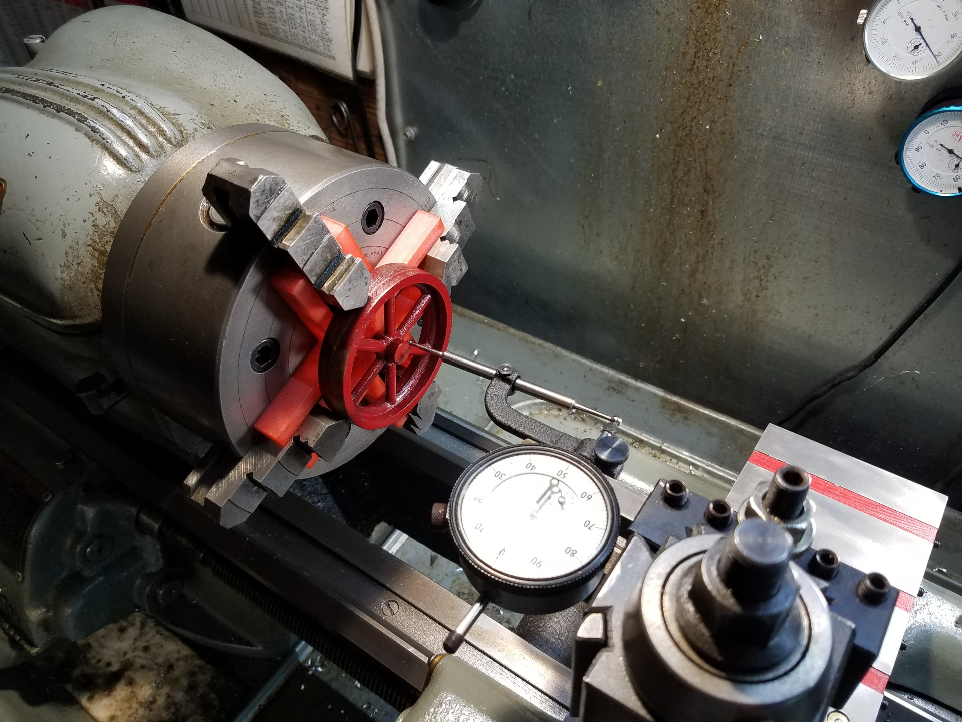
Back at the lathe, here the flywheel is being centered in the 4 jaw chuck and it's a PM Research casting, specifically the FWC-S7 #7 Flywheel Casting.
The red paint is something new to me as it is powder coated. A coworker does advertising laser work on the side and previously he powder coated the cups himself but nowadays buys them ready-to-laser. He casually mentioned that he was selling his powder coat gear and gave me a sweet deal on his entire kit. I'm still learning but I was able to get this flywheel coated and successfully cooked-off in the shop's EasyBake toaster oven. The great advantage of powder coat paint is it's durability. No problems machining this flywheel with no scratches or chips in the coating.
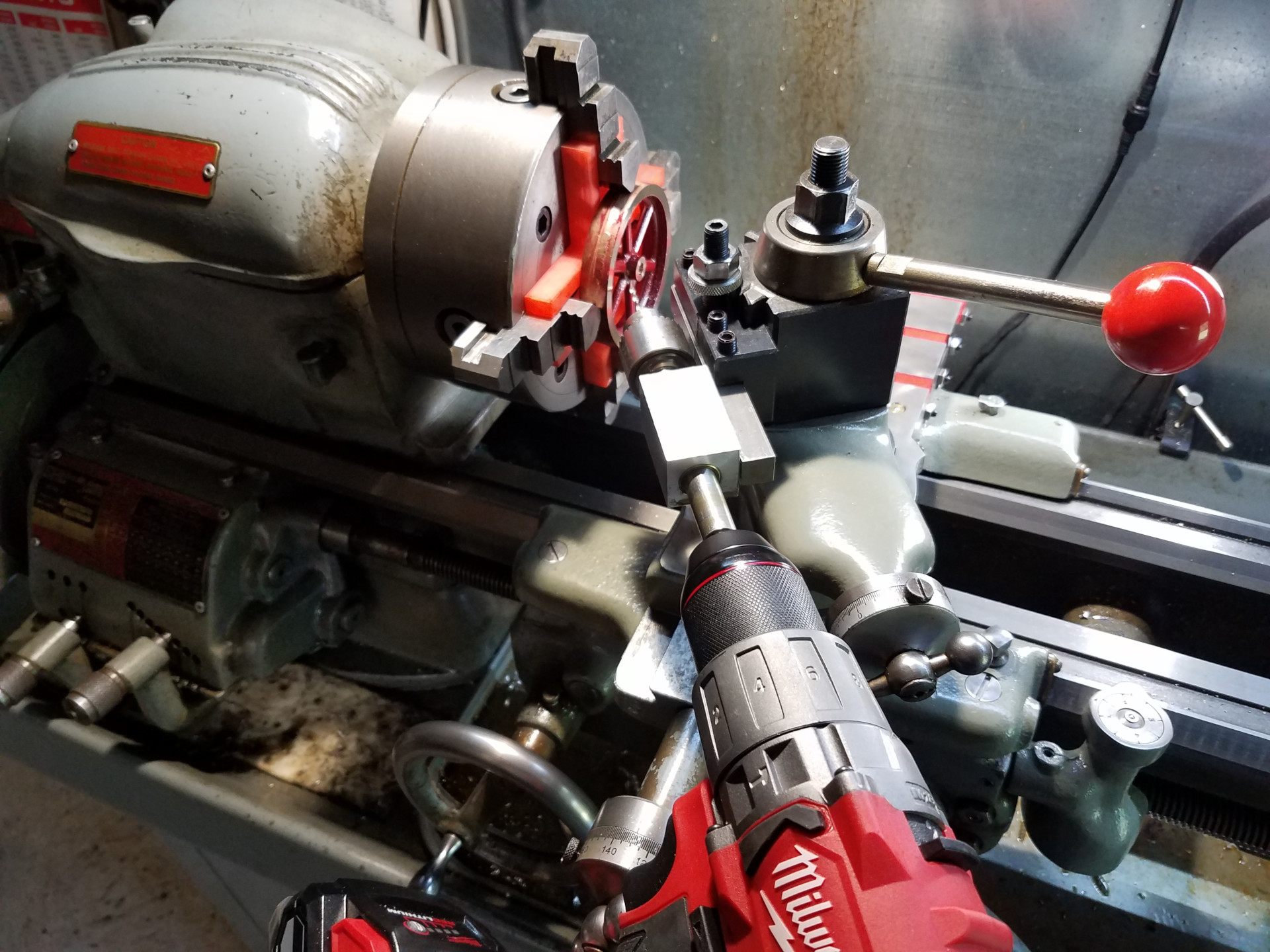
Here I'm drilling for the set screw without removing the flywheel from the chuck. The drilling device is basically a small chuck attached to a 1/2" shaft which is turning inside a long bronze sleeve. You move the shaft forwards and backwards while using a cordless drill to make the hole. The device is fastened to a QCTP holder so it's easily removed for access to change drills or taps.
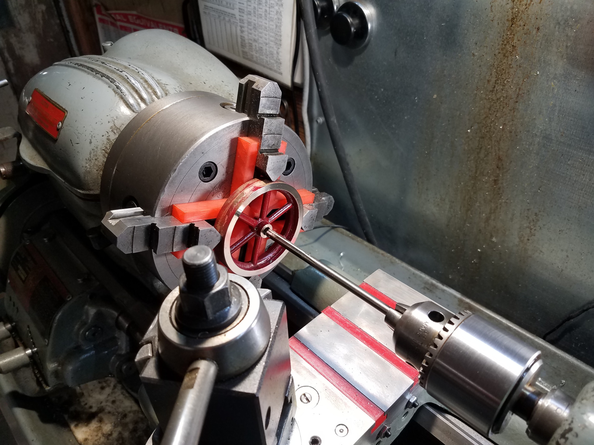
After the drilling and tapping for the set screw the axle hole is cleaned-up and finalized with a reamer.
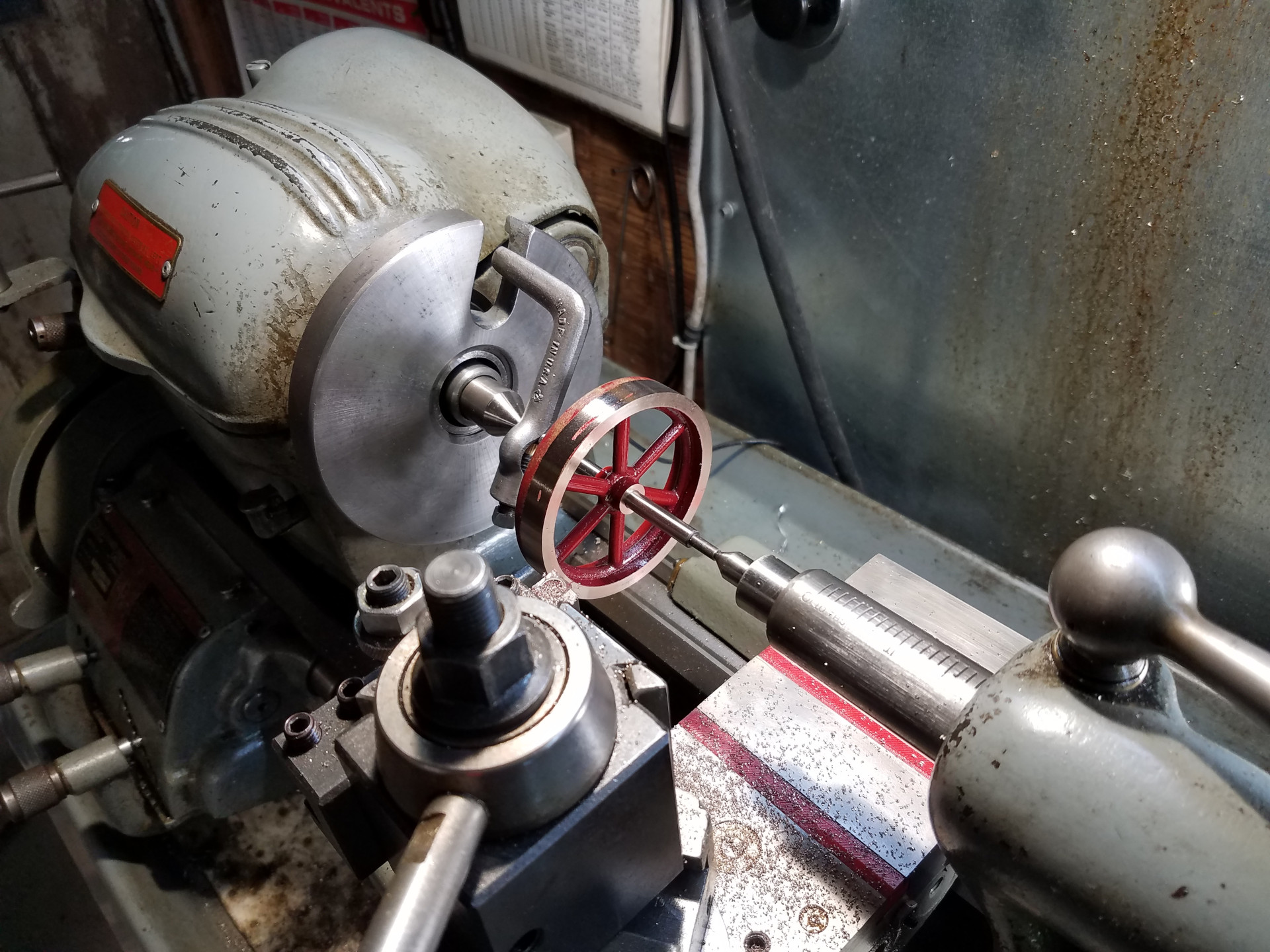
The lil Dake was used to press an arbor into the flywheel and then it is turned to size between centers. It's only a 1/4" arbor so very light cuts were used. When machining a flywheel, I try to use maximum effort to insure concentricity as the first and only thing most people will notice with a model engine is if the spinning flywheel is all pissed and wobbly.
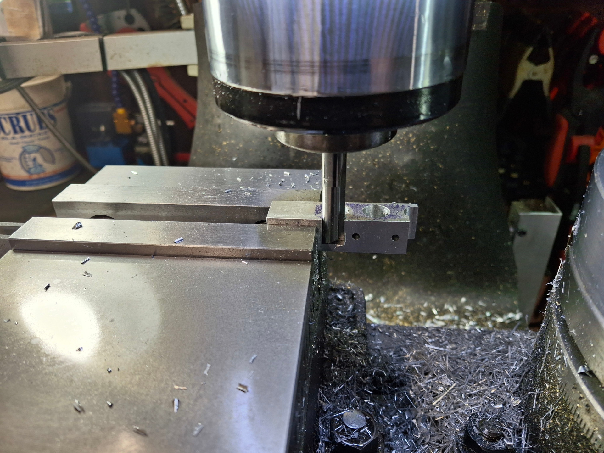
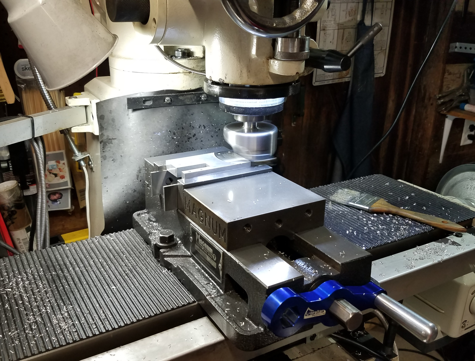
Here I'm working on the foot. The reason I'm "cutting off the branch I'm standing on" is because with both the vise and rotary table mounted on the mill table there is very little table travel on the left side of the vise. I was somewhat going by the scribe lines and didn't want to flip the part over. After this cut, I freed the top part of the foot from the stock with the band saw.
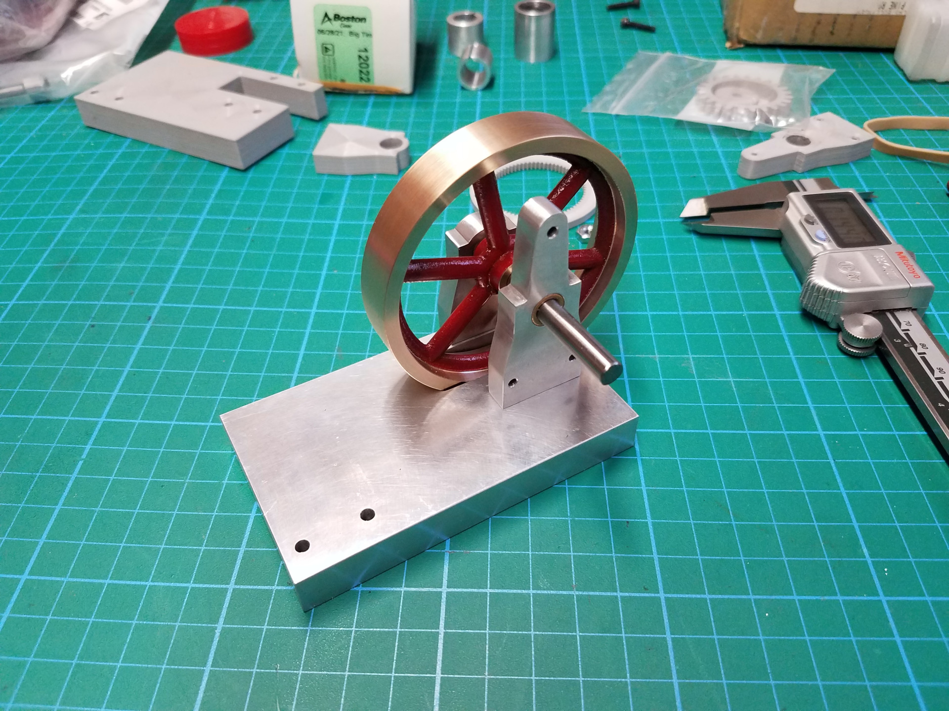
It's coming together!
The Elmer's Geared Steam Engine build will continue in the next article.