Construction of the Elmer's Geared Steam Engine continues in this article. A major piece of the project is completed which has many machined features: the engine cylinder. With that component completed, work starts on the many smaller parts of the engine like the steam chest and eccentric. The ER11 collet chuck is highlighted which is a very handy piece of kit for tiny end mills and drills. This engine build will be wrapped-up in the next article.
 Elmer Geared 12
Starting on the cylinder. Due to it's relative complexity, it's the most interesting part of the model. I started with a nice chunk of brass and faced it off to dimensions on all sides.
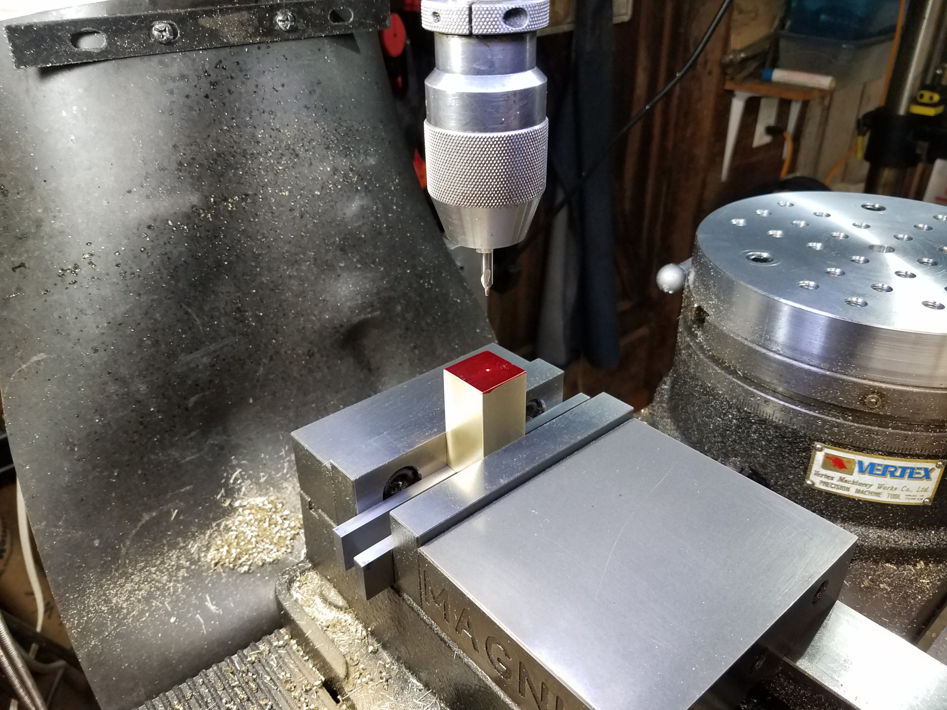
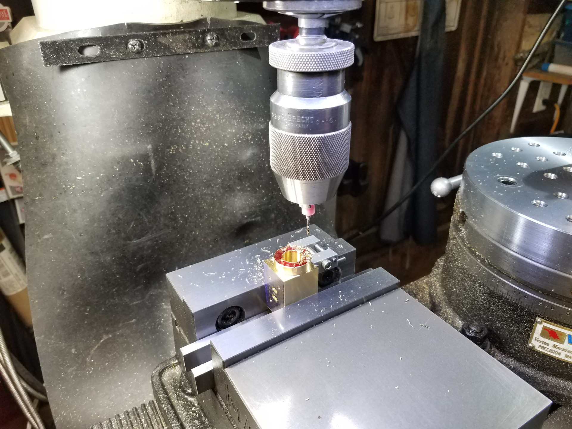
Here I'm center-pointing the cylinder location which, by the way, is not in the center of the stock so the DRO on the mill was used to find and spot the offset location.
 Elmer Geared 13
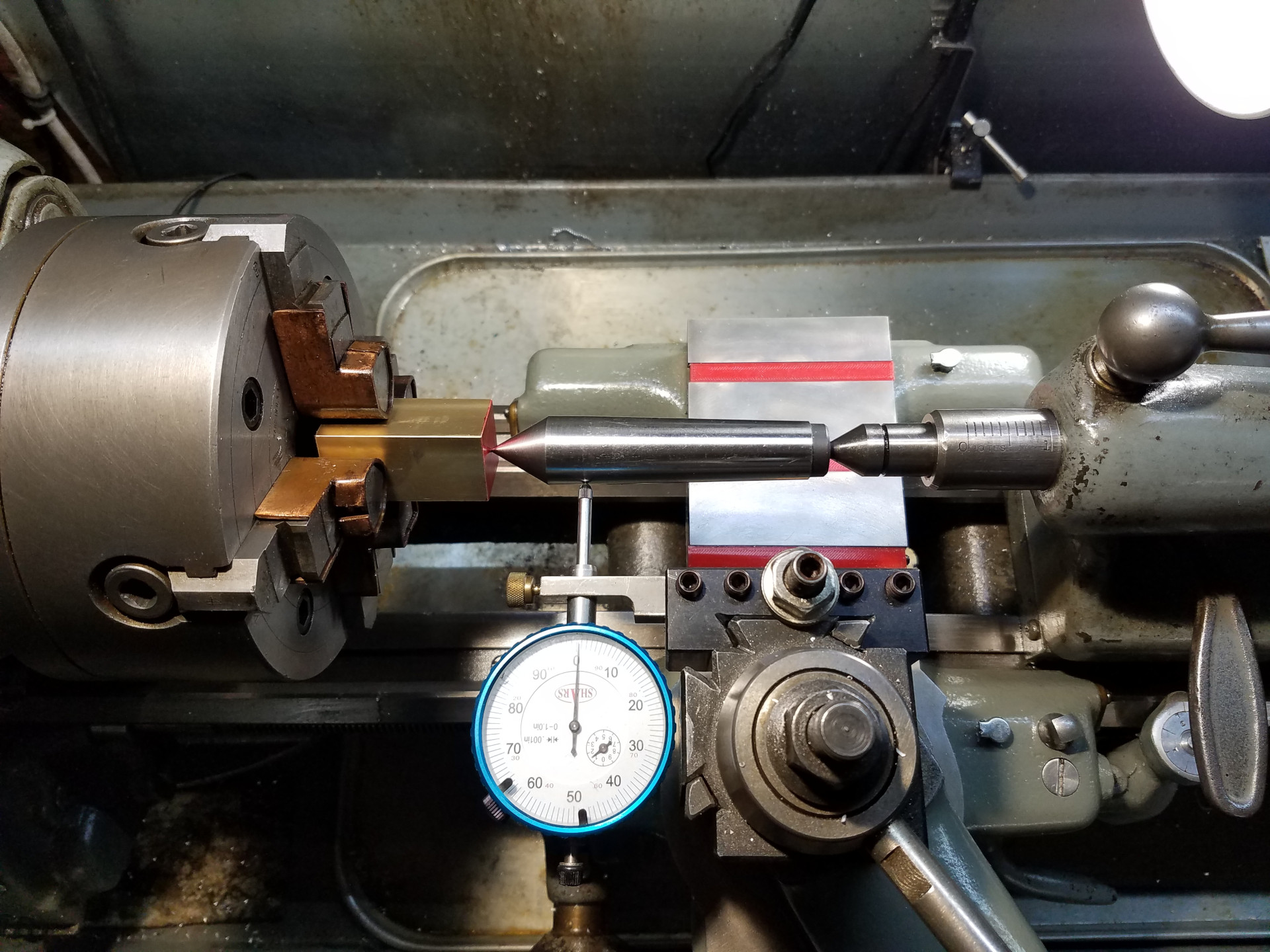
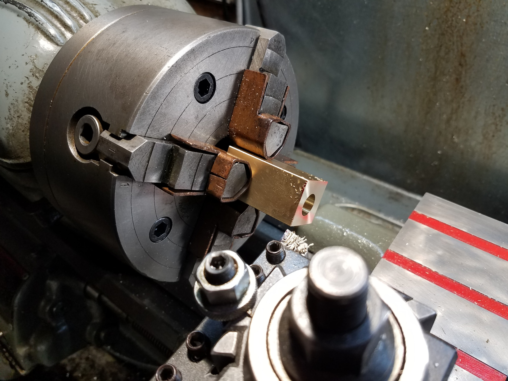
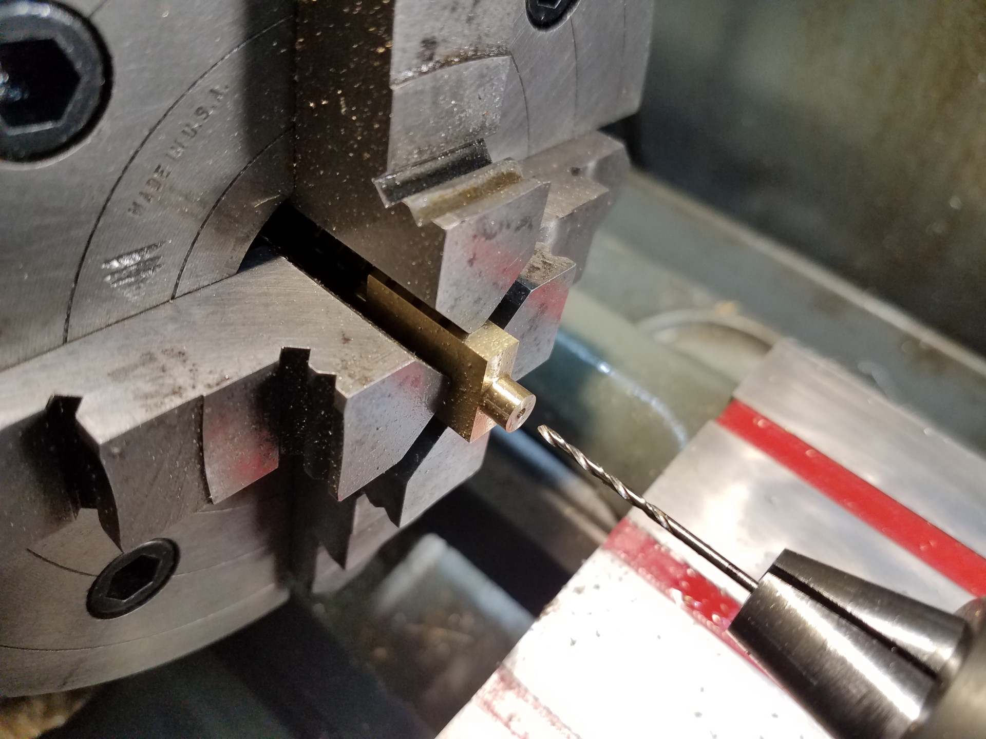
Back at the lathe, the drilled point in the stock is centered in the 4 jaw chuck using the dead center technique.
 Elmer Geared 14
And then the hole is opened with a drill.
 Elmer Geared 15
The cylinder only has a 1/2" diameter hole but is almost 3 inches long which is kind of long for the piston size. I could have reamed it, but I was able to make this small carbide insert boring bar do the job. The finish inside the hole was excellent.
 Elmer Geared 16
Facing off the front of the cylinder. It's always a good idea to face off the inboard face of a cylinder in the same setup as the hole was made because you'll never get the two features more perpendicular.
 Elmer Geared 17
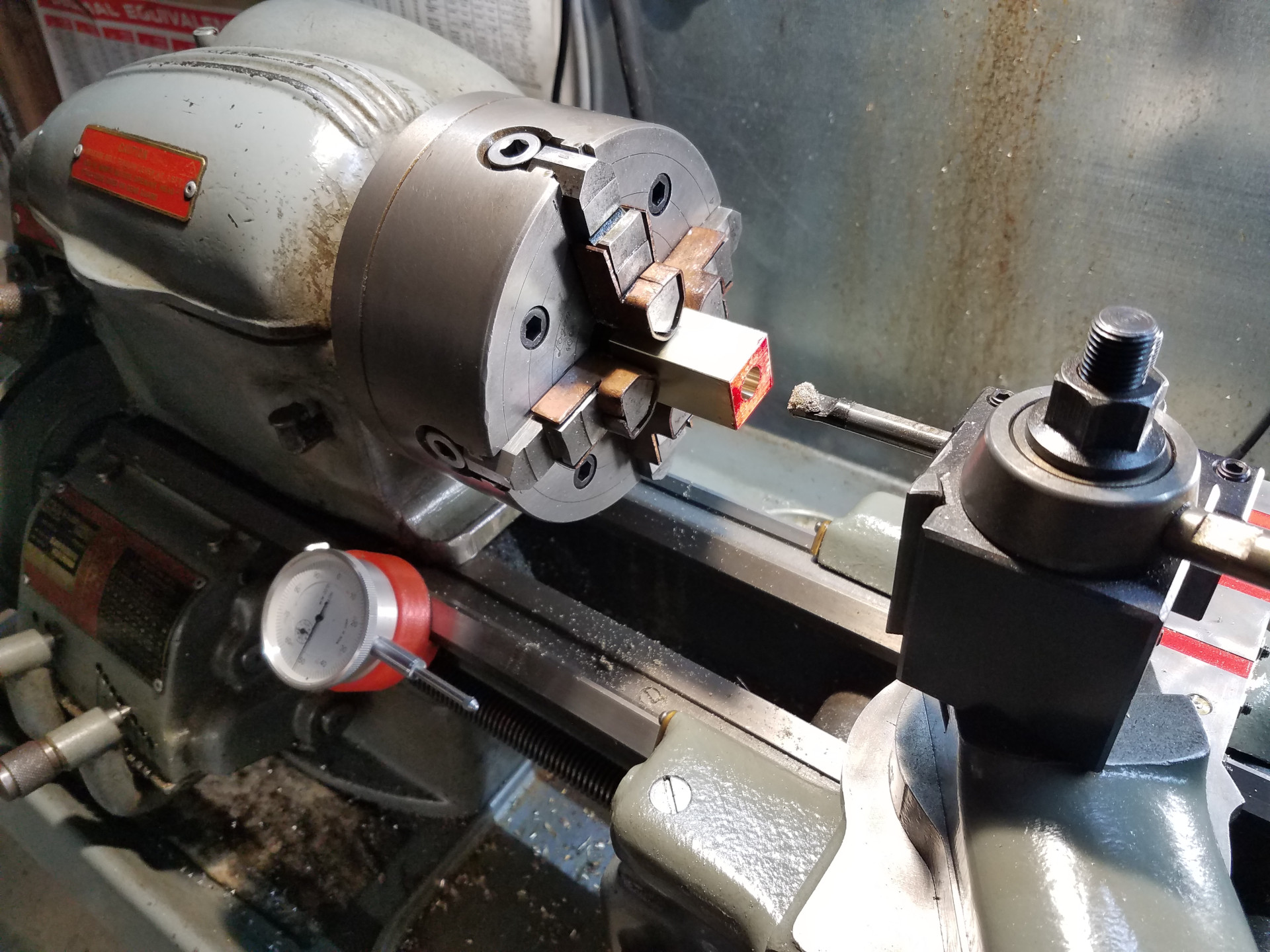
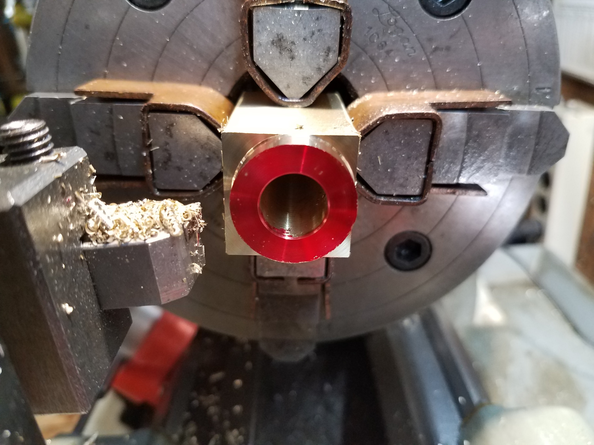
The cylinder was turned down to the plans and here you can plainly see the hole offset. I also marked this side red to make sure it's used for the inboard head. The cylinder was then flipped around in the chuck and the other side was turned down.
 Elmer Geared 18
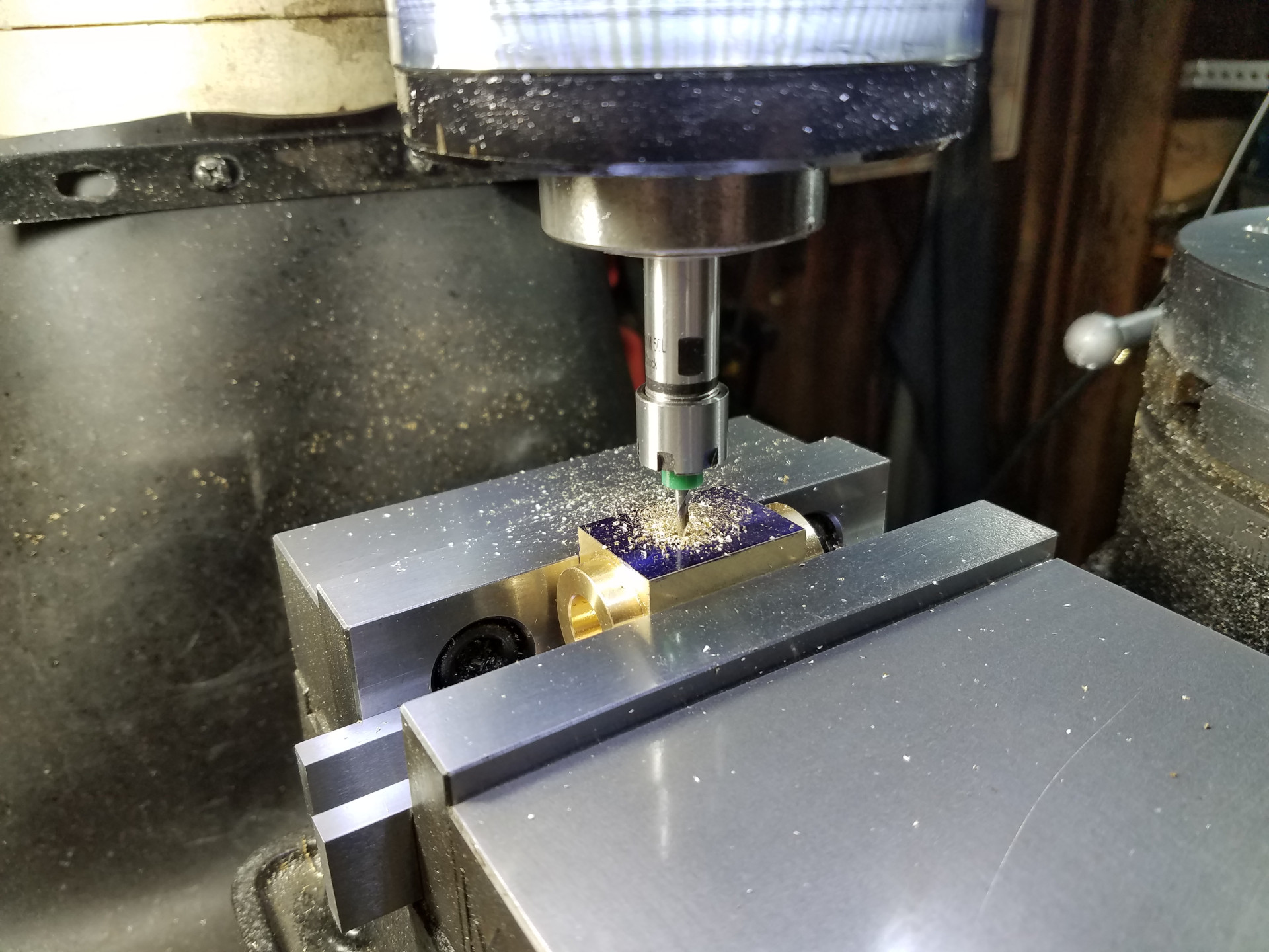
Back at the mill cutting the exhaust ports with a 3/32" end mill. I'm holding that end mill in a stubby ER11 extension. This is very handy as it gives you enough visual clearance so you can see what you are doing compared to holding the tiny end mill directly in the spindle. I also have a longer ER11 extension for drilling holes in hard-to-reach places.
 Elmer Geared 18_5
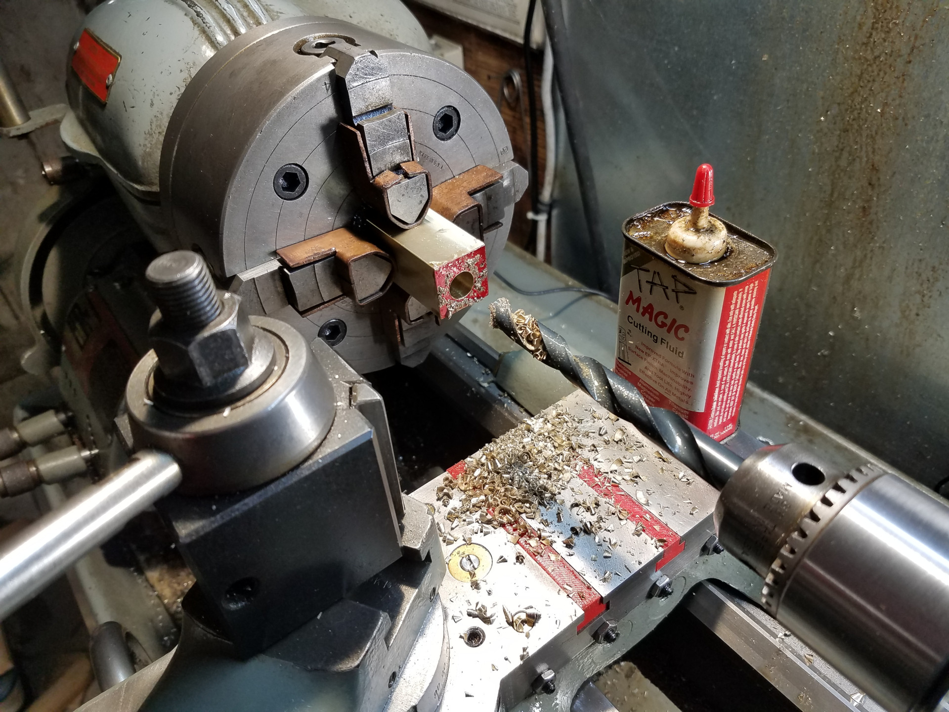
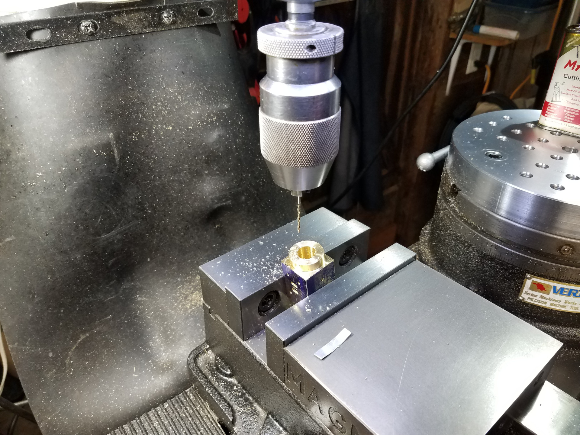
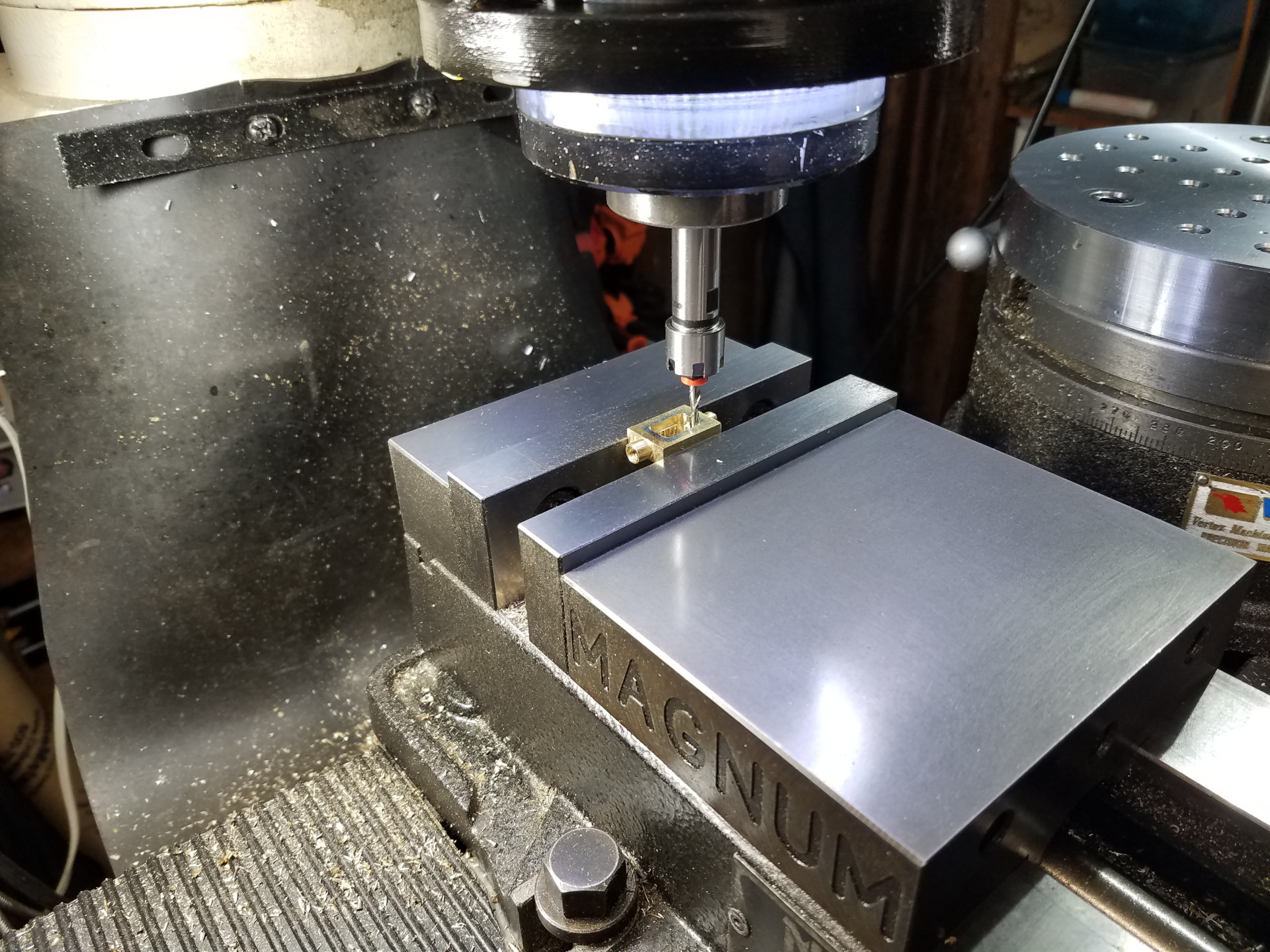
Drilling the exhaust passage from a cylinder face to the exhaust port which is always a tense moment. The drilling angle suggested by Elmer worked fine and the small brass sheet is inserted into the exhaust port while drilling so you can easily feel when the drill breaks into the port.
 Elmer Geared 19
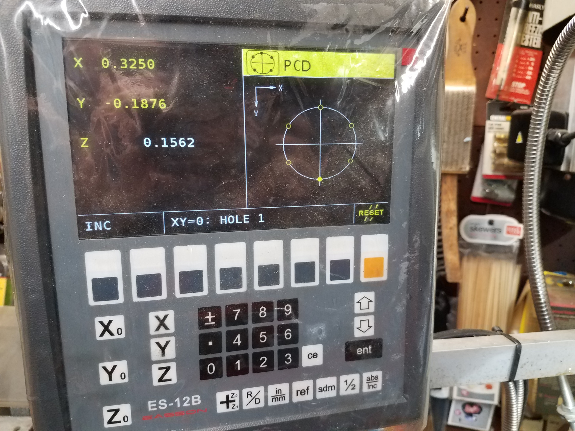
Drilling the bolt hole circle for a cylinder head using the DRO.
 Elmer Geared 20
This is what the PCD function looks like on this DRO which I think is a bit more intuitive than the older displays that only feature a numerical output.
 Elmer Geared 21
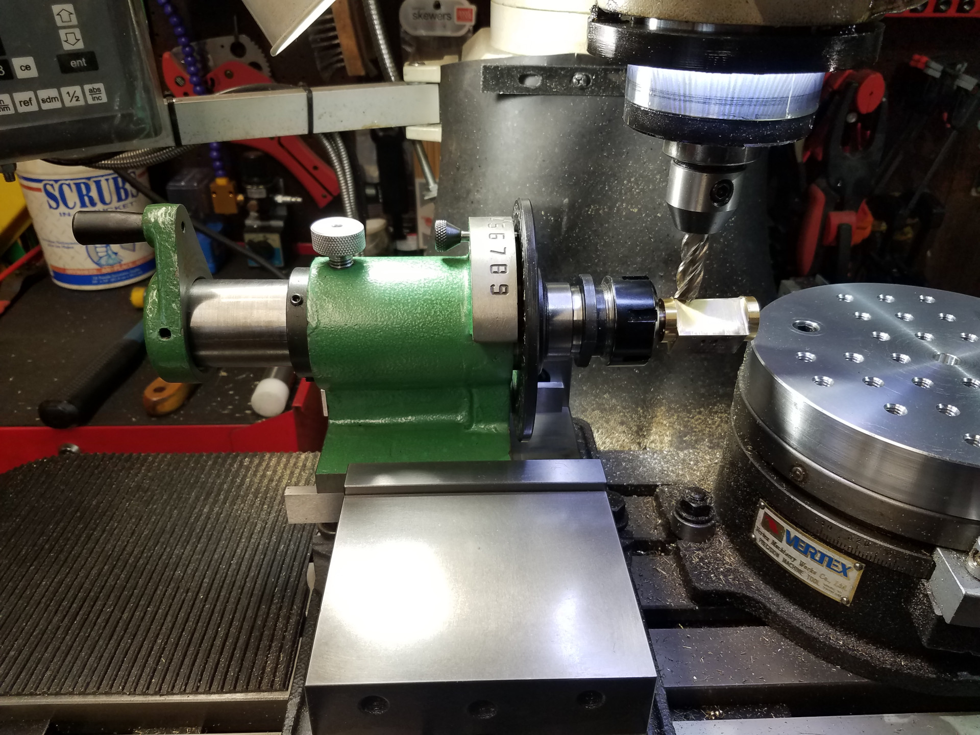
Awhile ago I milled the bottom of this Spindexer so it would sit accurately in the milling vise. Here I'm using it to hold and turn the cylinder so I can mill the cosmetic rounded part between the cylinder faces. It's not really made for this type of work, so take lights cuts and mill slowly as you don't want to spoil the work this far into the job.
 Elmer Geared 21_5
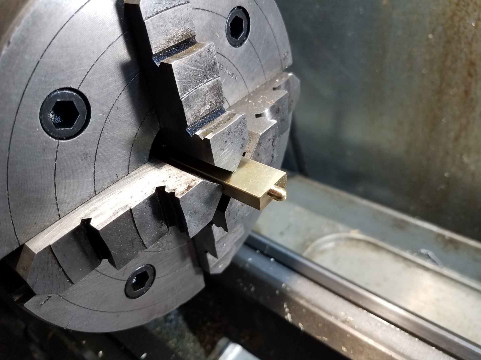
For the steam chest, a brass bar was held in the 4 jaw chuck at the lathe. Formed the round bit with a file on the outboard side and it came out good enough on the first try.
 Elmer Geared 21_6
The proto steam chest was then flipped over, turned to length and the other end machined. Drilled the 1/16" hole almost to the end of round bit on the other side which wasn't exactly fun. It might have been better to mill out the inner part and then drill out these end holes at the mill.
 Elmer Geared 22
The steam chest getting opened-up at the mill.
 Elmer Geared 23
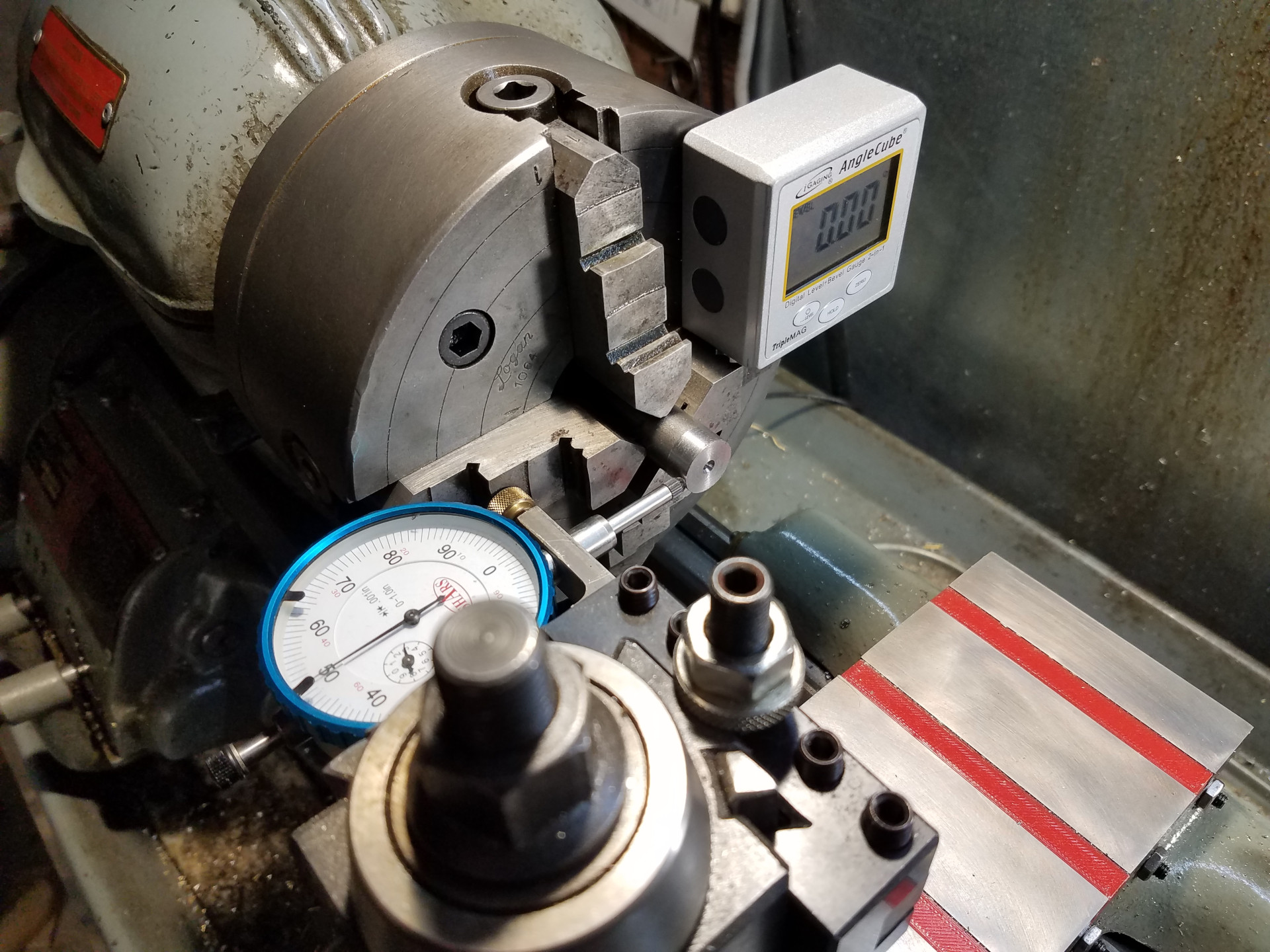
While the 4 jaw chuck was installed at the lathe, the eccentric was setup and then machined. I always enjoy making these as it seems somewhat magical while you are turning the offset.
The Elmer's Geared Steam Engine build will be completed in the next article.