The Elmer's Geared Steam Engine build will be completed in this article. The valve rod is constructed with an interesting technique for turning small diameters. The gears are installed and lapped together for smooth running and finally assembly commences with gasket making and switching over from screws to studs. A piece of clear acrylic is crafted to use as the valve cover so the valve action can be observed while the engine is running.

Working on the valve rod. One thing I wanted to show is that it's usually difficult to turn such a long, thin rod without some form of support. In fact, the first time I turned the rod down using multiple passes it snapped off from the parent stock. This time I used a technique I seen described elsewhere which was to take it all in one shot. So at first I just turned down the corners of the square bar to get a good measurement and then the rest of the stock was removed in one pass. It worked great with the valve rod measuring right on dimensions throughout it's length.

Using the Neil Butterfield inspired sliding tap/die holder for threading at 2-56.

The valve rod nut needs to fit nice and tight.

Working on the gear arm at the rotary table. Tried out a new rotary fixture plate during this project and found it worth the bother of making it.

Some more clean-up of the gear arm at the lathe. This will be soldered onto the orbiting gear.

When I setup the gears in the bearing holder, I noticed a slight tight spot while turning the crankshaft.
One would think the factory gears would be perfect, so probably the tight spot was due to one of the gear teeth of the orbiting gear getting knicked while machining when the gear popped out of the holder I made. In any event, some lapping compound on the gears and less than a minute's work with a drill turning the crankshaft totally solved the problem.
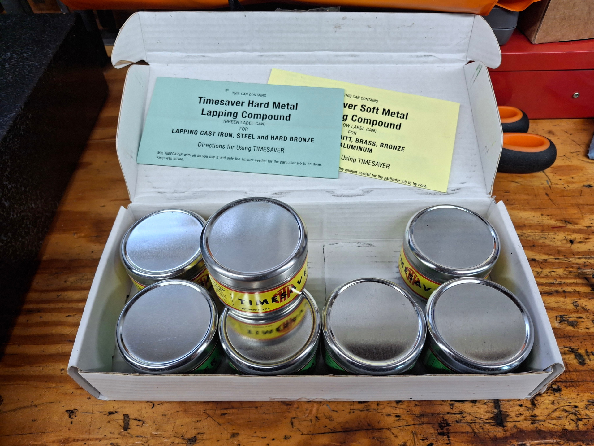
I used the Timesaver lapping compound which is nice because it's guaranteed not to embed into softer materials. It comes as a powder that is then mixed with oil for use. The test kit shown is an assortment of lapping compounds for both hard and soft metals and should last the average modeler a long, long time. I tried to make the moving parts, like the eccentric / eccentric strap fit, a tad on the tight side and then used the lapping compound while working the parts for a perfect fit. I think this is a more civilized approach than some of the madmen on Youtube who "break-in" their engines by turning them strapped to a lathe for hours on end. Madness!

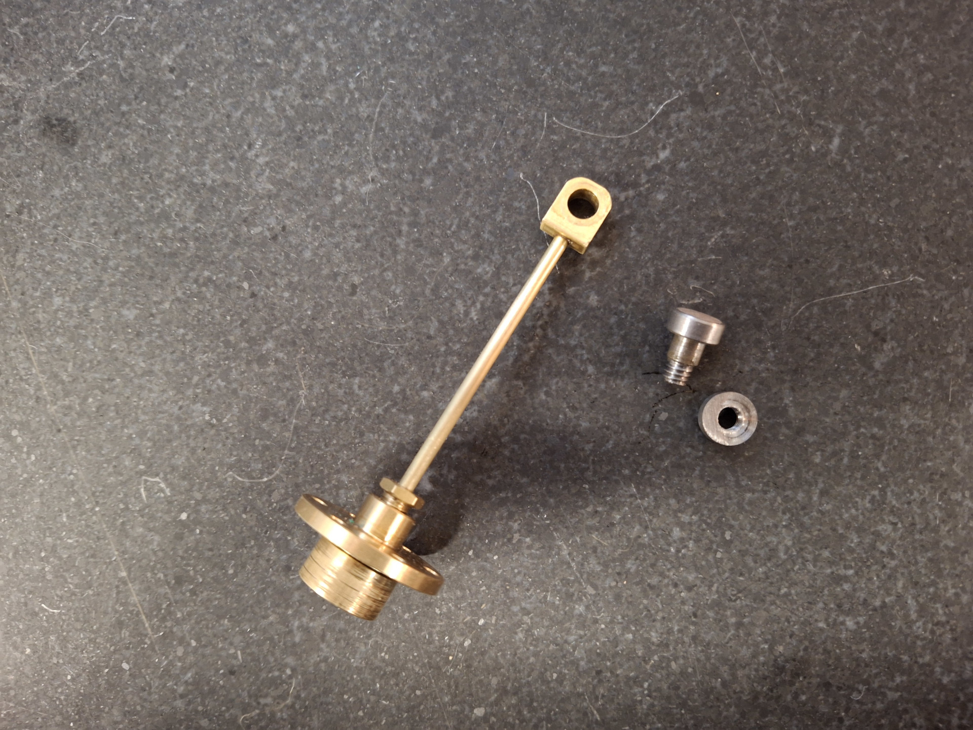
Finishing off the valve. Originally the valve was a bit too high to fit properly (assumed a dimension), but it was an easy fix as the bottom just needed a bit milled off. The valve nut was installed so the valve wouldn't get squashed while being held in the vise. By the way, that's a smaller vise held with the regular milling vise as the valve is under a 1/4" square. You know when the ER11 collet looks big that the parts are getting small.

Getting parts attached to the cylinder. I'm using the Loctite thread sealer to "glue" the valve plate and steam chest to the cylinder in the proper location that way I can loosen the bolts to remove the valve cover and not have those parts loose their location. Eventually I will switch to a clear acrylic cover to see the valve moving as shown in Inky's engine. If you look closely at the valve plate you can see some polishing from the valve. Looks like it's running right on the money!
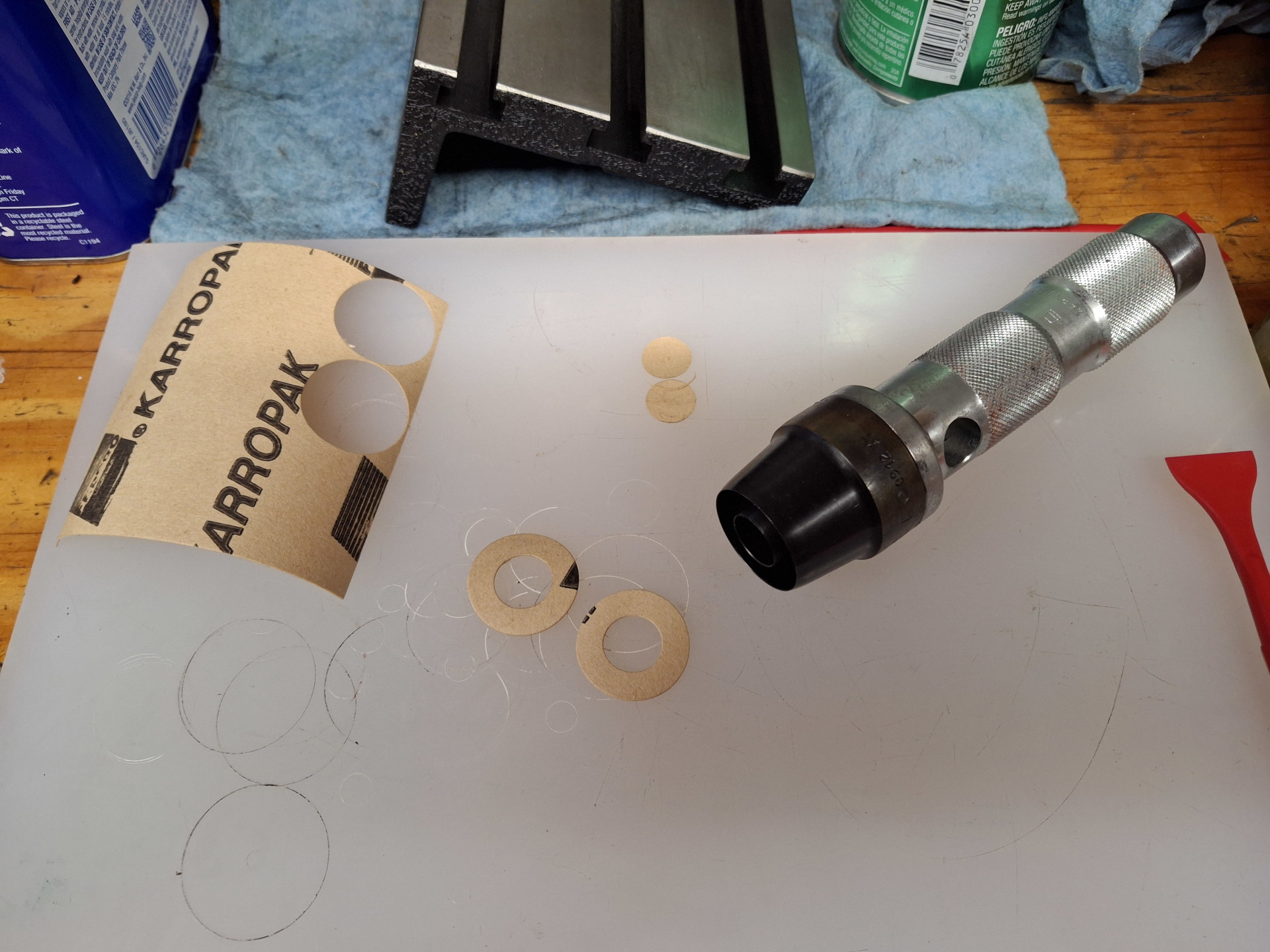
Punching out the cylinder gaskets in one hit with a dual-head Mayhew hollow punch. Bought this set used because it's made in France and somewhat salty here in the states. Excellent kit if you see one.

More work on the gaskets. I had bought one of those leather punch tools to try with the small holes but totally forgot about it.
Decided I wanted to round-off the end of the piston rod but didn't want to take it apart as the rod packing was set and everything was working correctly so I made a filing button. Bit of work, but they are an almost idiot proof way of rounding parts like this.
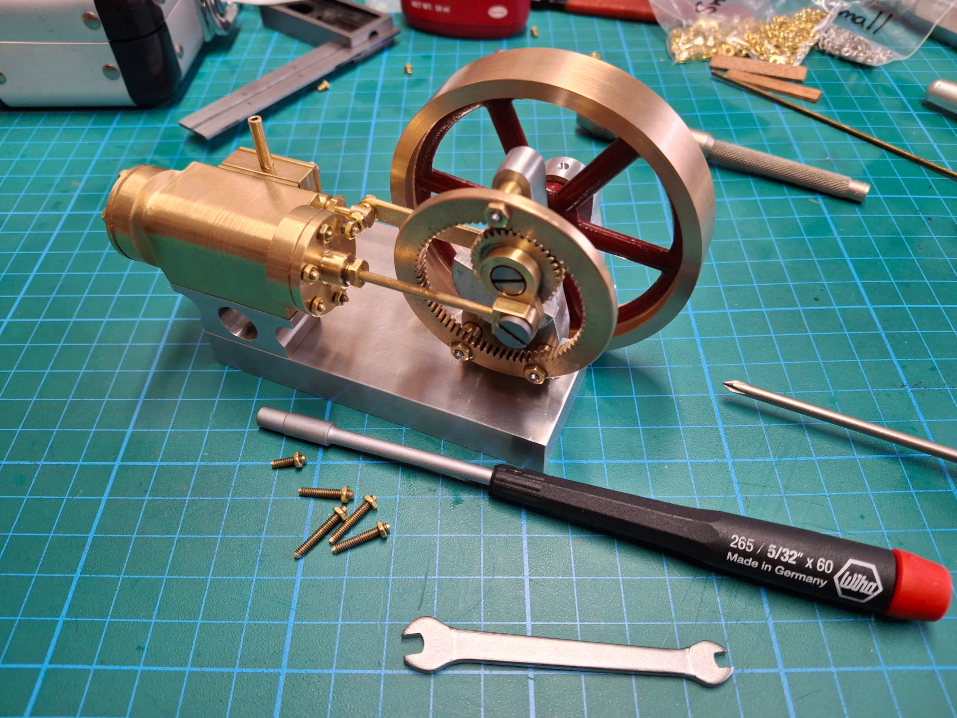
Reaching the end of the build so I'm replacing the Phillip screws I was using during the build with studs which are just nuts loc-tited to a piece of threaded rod. All the nuts I used on this model were 2-56 narrow-profile bought from McMaster-Carr. I'll also be adding wood lagging to the cylinder.
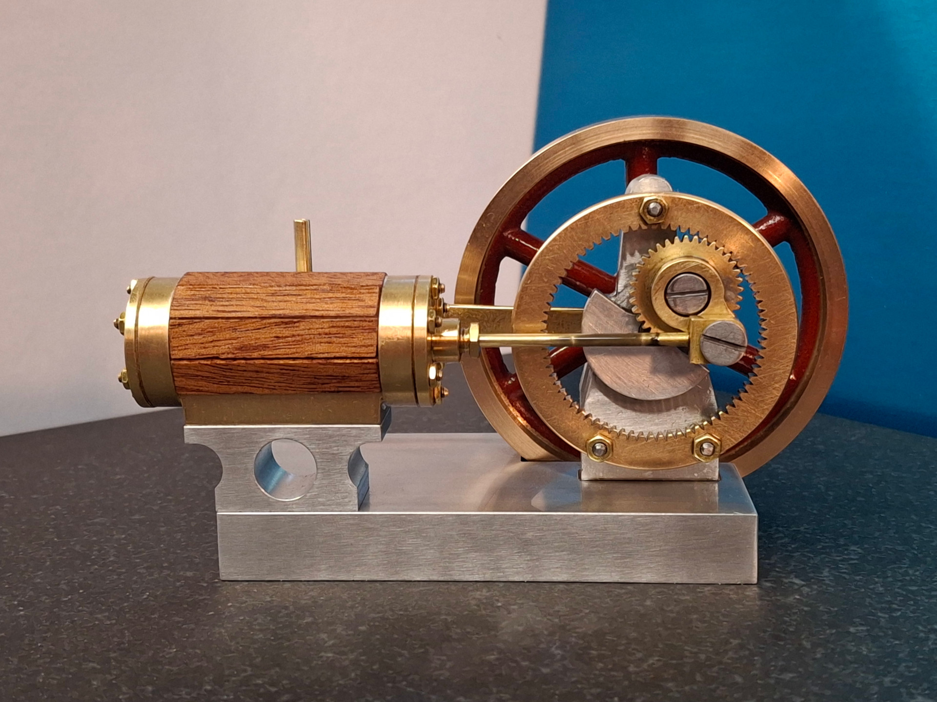
The completed Elmer's #5 Geared engine. Here you can see the doll house planking used as cylinder cladding for a cosmetic touch as shown in Inky's build. I just used CA to attach the planking as I'm not planning on running this engine on steam.
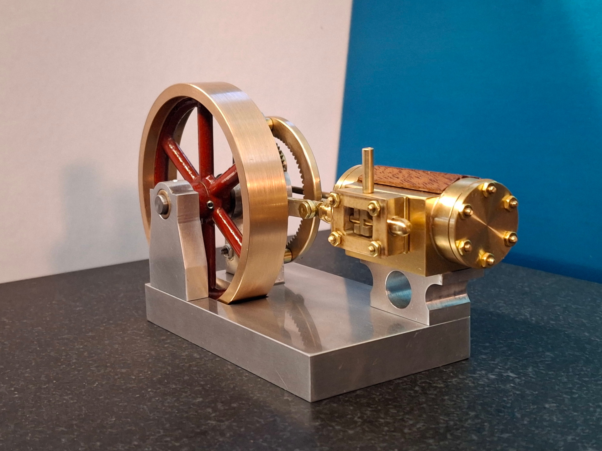
The acrylic valve cover is yet another idea from Inky's build. It's interesting to watch the valve working while the engine is running which nicely complements the trick gear arrangement on the other side.
A short video composed of three different views of the engine running on air.
Overall it was a very enjoyable build without any major difficulties. Elmer's drawings were spot-on and the engine ran well even at the first assembly. Probably the most important new technique (for me) used during the construction of this engine was modeling the project in CAD and then using that model to produce shop plans or 3D printed components for reference. That definitely reduced the bone-headed mistakes.