When you are installing DRO scales, they must be placed so that they are working within the same plane as what they are measuring. The instructions provided with the scales state they must be parallel and perpendicular to the machine slide movement within 0.1mm (.004"). Unfortunately, most of the cast surfaces of the mill are not square to the machined surfaces, mostly due to pattern draft. We will have to install square surfaces onto the mill for scale attachment points.
Now would be a good time to recommend another Doubleboost video series. Here he is installing a DRO system onto a mini-mill, but many of the same design considerations scale-up to the DRO install on this Grizzly mill.
Scale leveling pads very similar to what was described in the video will provide the parallel and perpendicular surfaces to mount the scales.
The controller will soon be needed, so it's time to get the bracket mounted. The left side of the mill was chosen because it's more convenient for me.
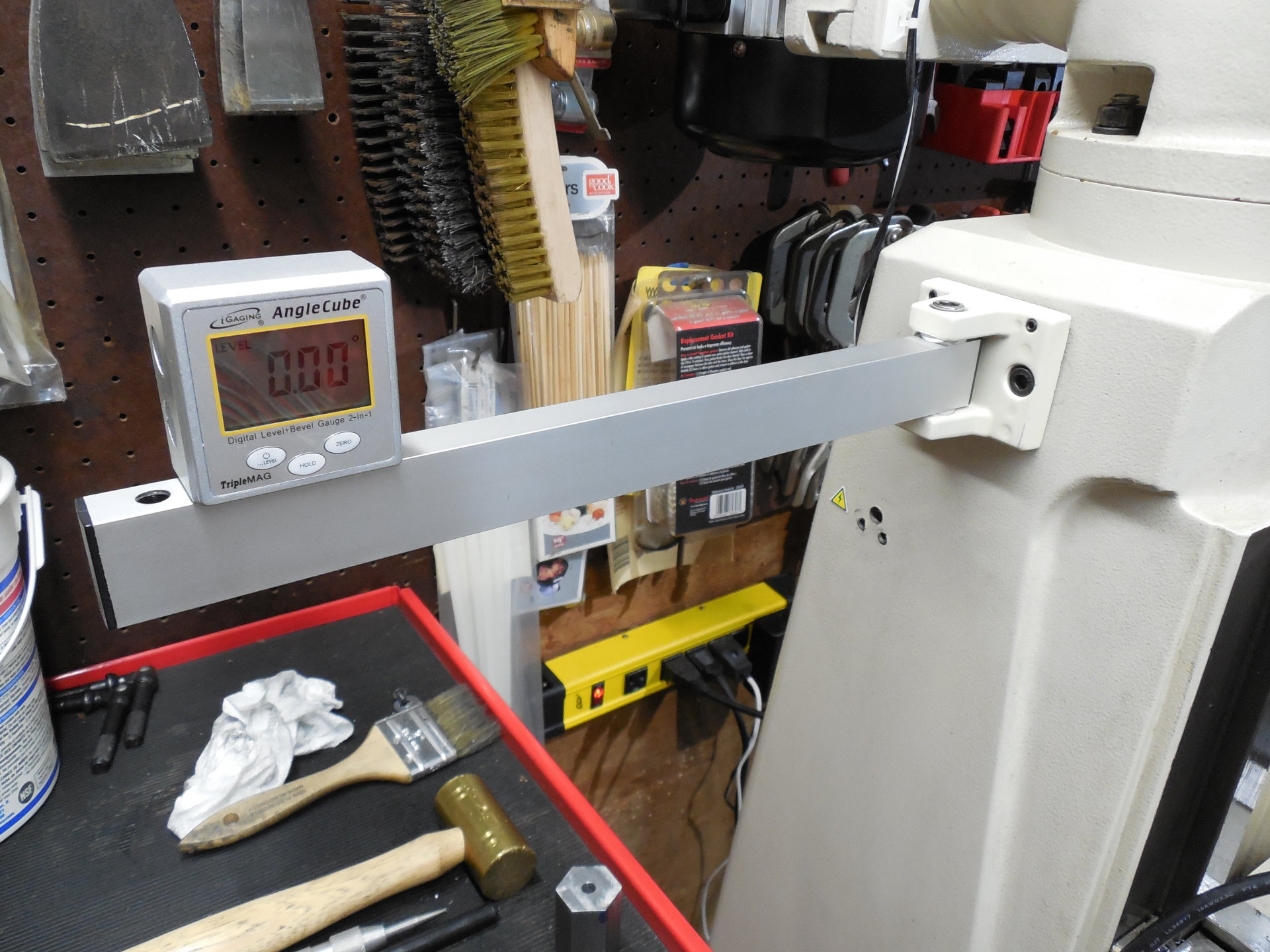
The controller bracket from the kit uses allen screws to to level the arm which is very similar to the design that will be used for the scale pads.
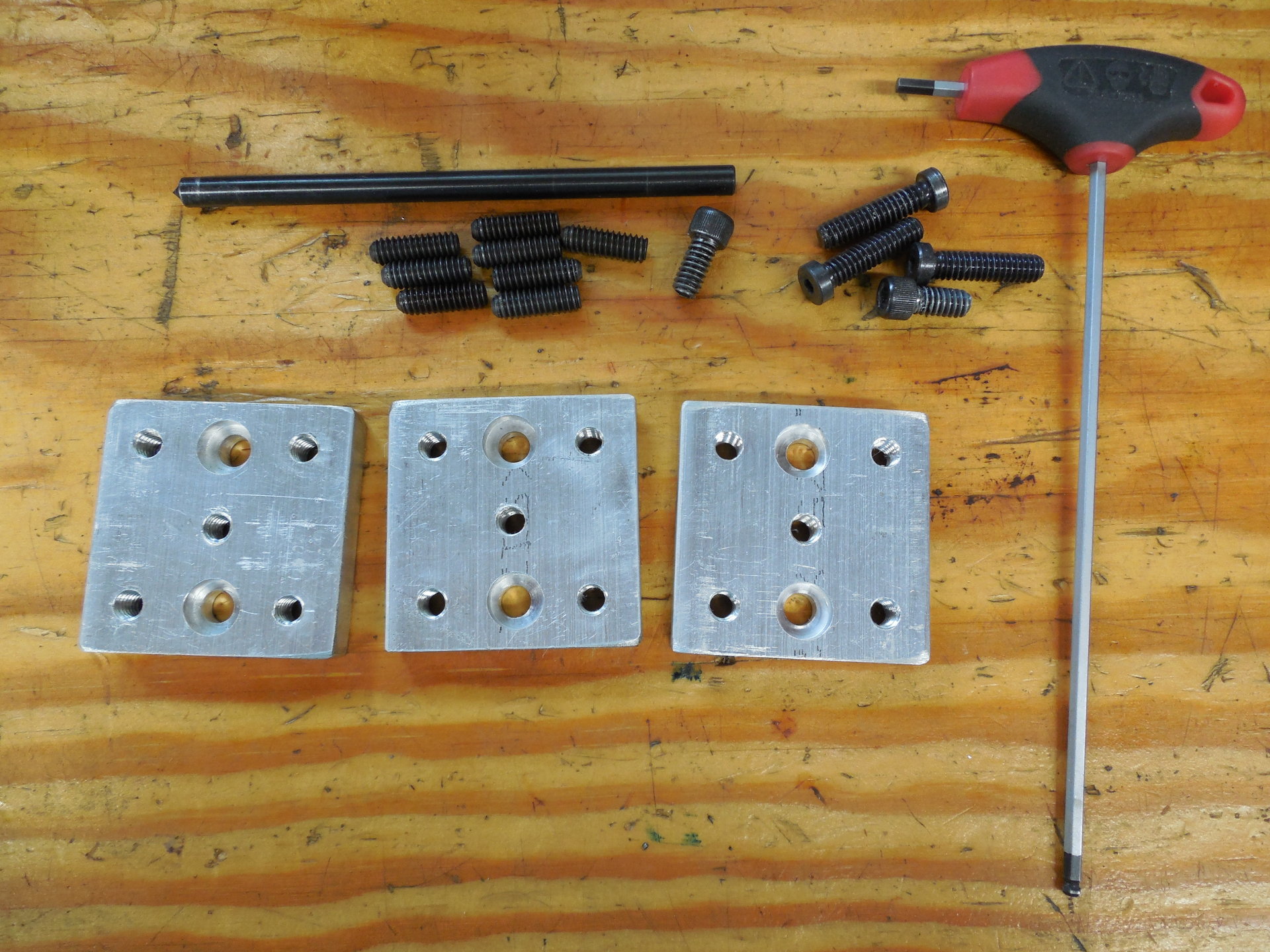
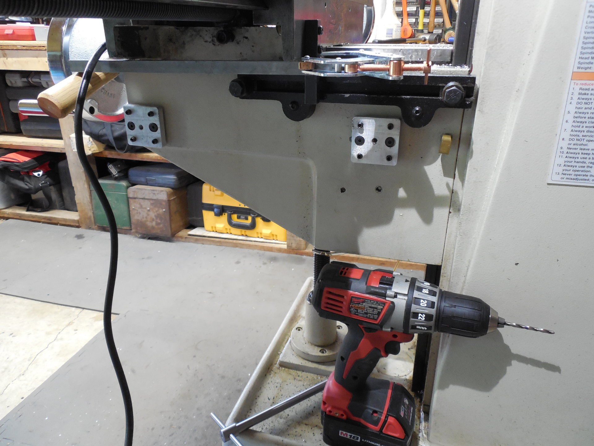
Here we have a few of the scale mounting pads that were produced during a small production run. The four tapped holes in each corner are for the allen screws which will level the pad to the plane of the slide movement. The tapped hole directly in the center of the pad is for attaching the scale back plate. The two counter-bored through holes are for the mounting cap screws that will be attached directly into the mill frame via a tapped hole.
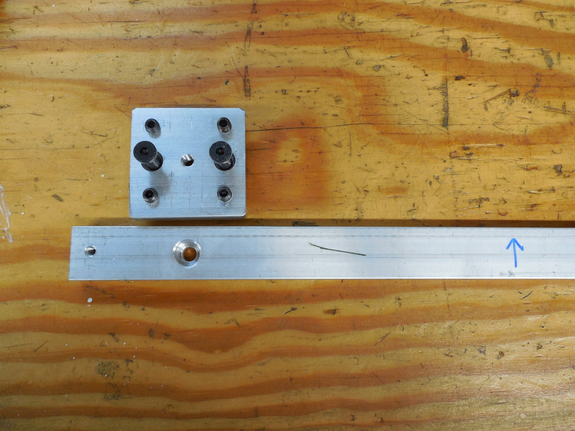
Here the hardware is inserted into the mounting pads. The scale back plate shown was provided with the scales.
The mounting pad, when attached to the mill, is extremely rigid when all the allens screws and mounting screws are tightened. A solid attachment point for the scales is very important for accuracy and repeatability.
The Y axis should be the easiest to install so that was chosen as a starting point. Since most of the real estate on the left side of the knee was already consumed with the one-shot oiler and knee lock knob, all the DRO hardware will have to go on the right side.
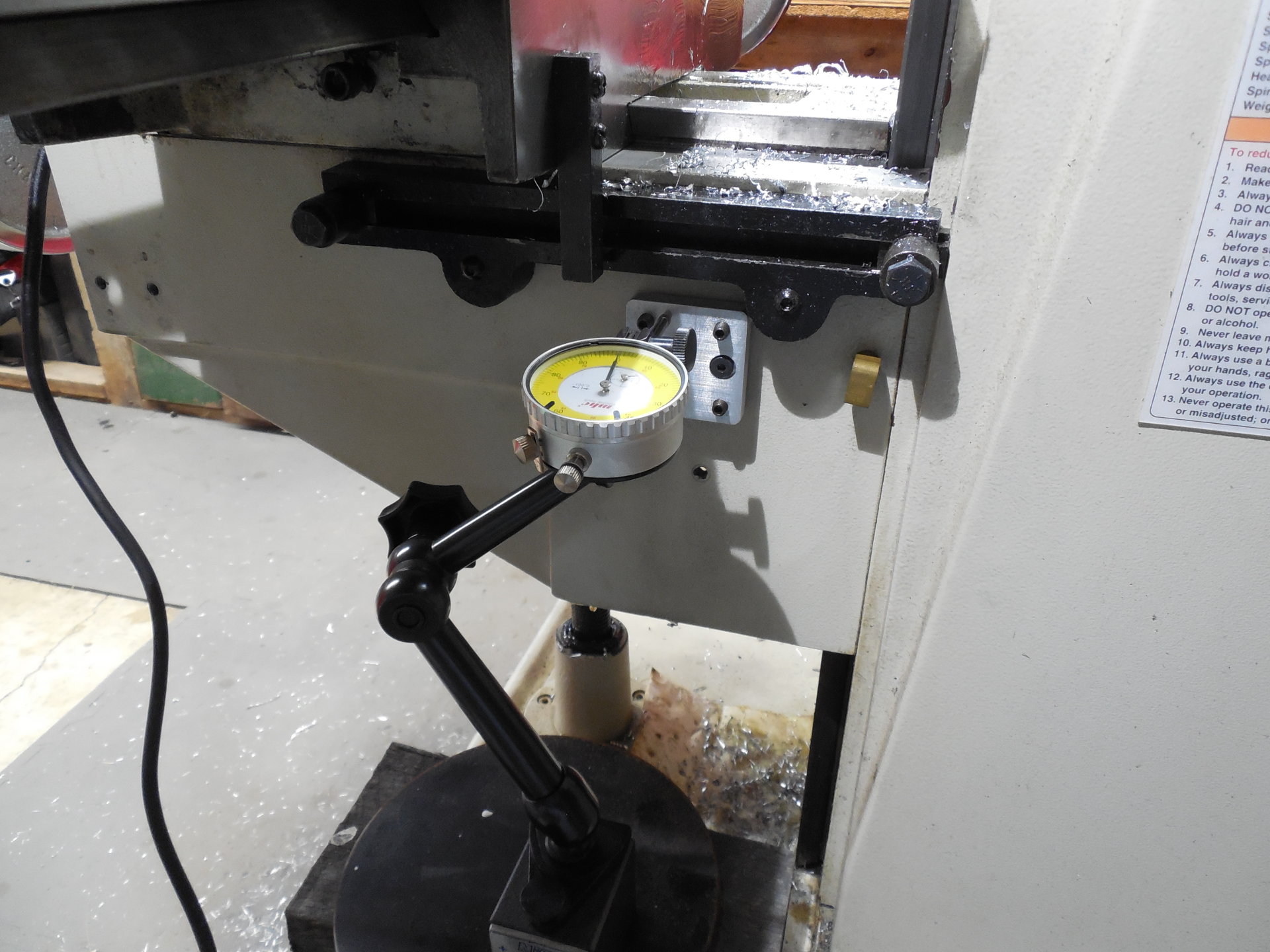
Here one scale mounting pad has been attached to the knee. I'm using a dial indicator to get the pad aligned, adjusting the allen screws in the corner of that pad until no movement is shown on the needle when moving the knee or saddle. When doing a DRO installation, you will spend a great deal of time sweeping mounting pads and scale back plates.
The Y Axis hard stop setup is pretty much stock, although some custom tee nuts were made for inside the Y Axis stop casting.
The other scale mounting pad has now been installed. Here I'm setting up a bar that will eventually attach the scale's reader head to the saddle. Tapped holes in the bottom of the saddle will hold the bar.
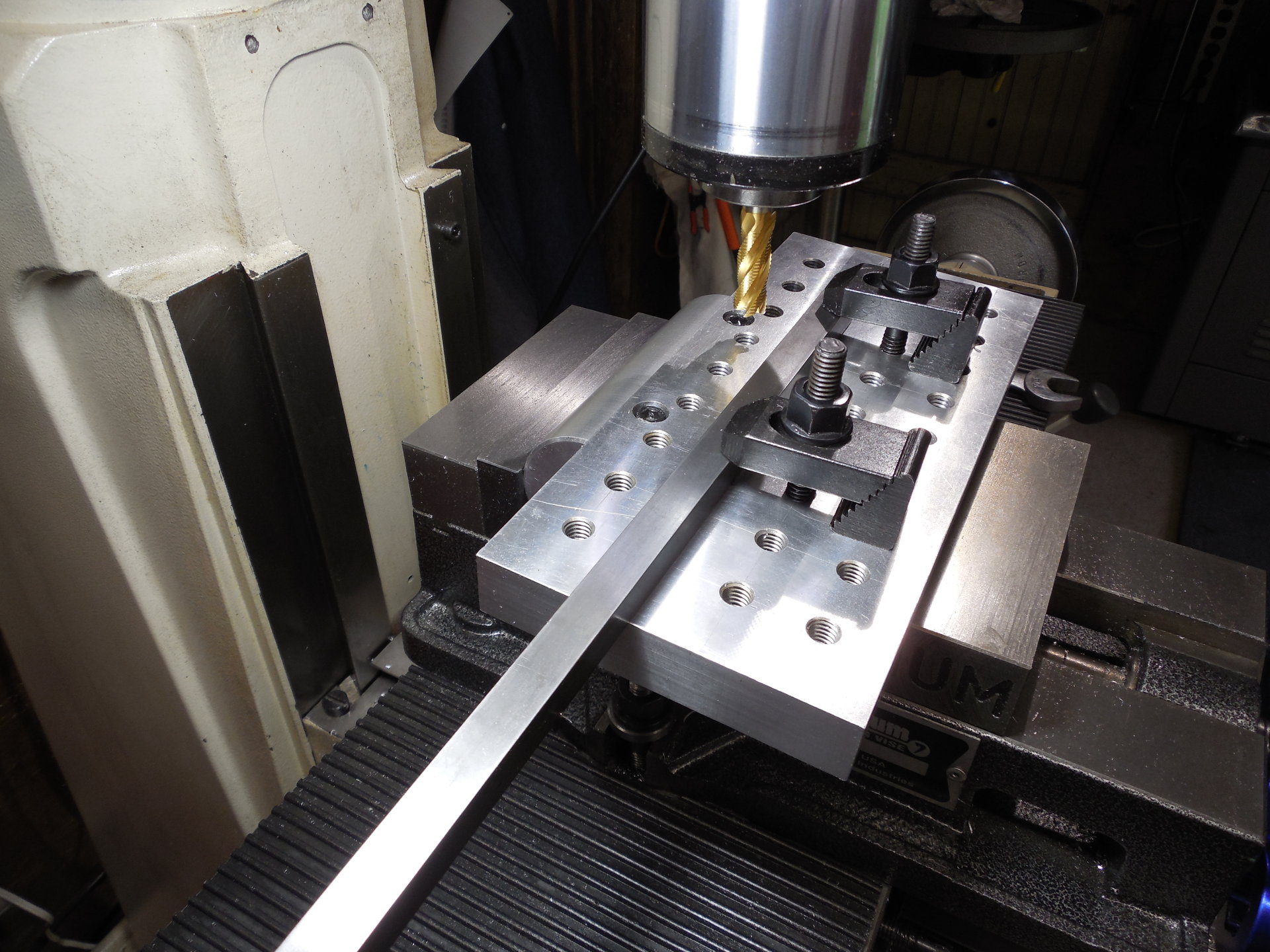
In order for the bar to fit properly, an angled slot needs to be milled in the bar to match the angled bottom of the saddle. This fixture plate is attached to a large aluminum round so it can be tilted in the vise to allow that cut. This mill's head doesn't nod so this is one way to perform this operation.

And here's the entire Y axis DRO scale installed. While the scale does have seals at it's bottom opening, it's important to have that part of the scale pointed away from any source of contamination from either oil or chips. Glass scales that get dirty inside don't work very well. The cover has also been installed to further protect the scale from oil.