Time to wrap-up the VFD installation for the South Bend 10K lathe by installing the motor into the lathe cabinet and making a custom mounting bracket to mount the VFD and avoid any unnecessary holes. The VFD was installed in a slightly unusual position so it is discussed why I didn't go with a more typical controller spot and why this was the best position for my usage. Also an emergency stop switch was installed that will completely kill power to the lathe.
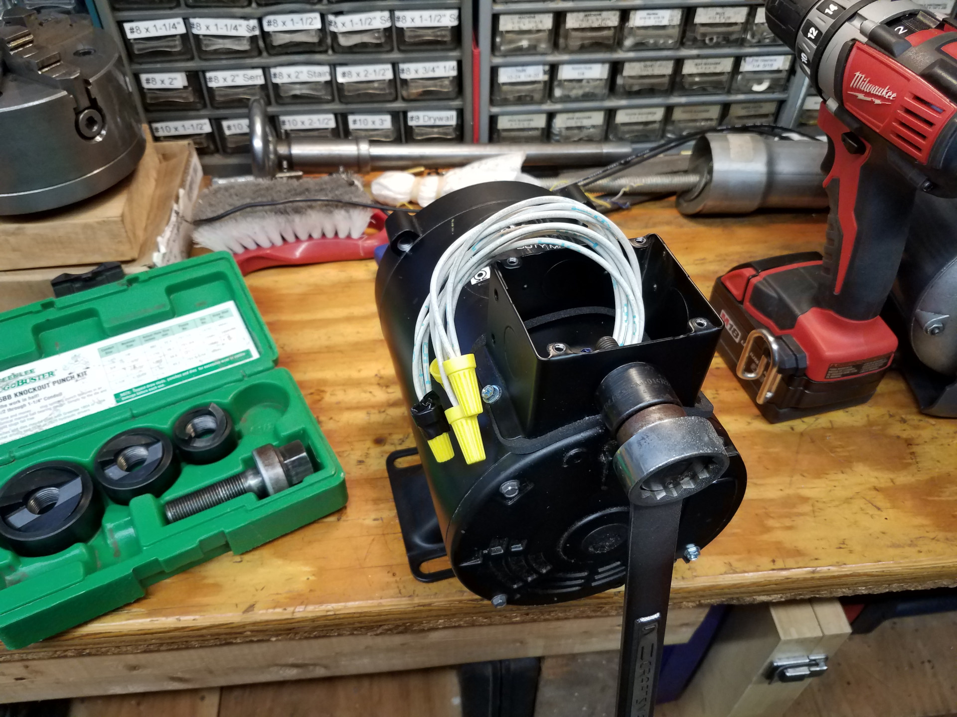
While the peckerhead for the motor has three conduit knockouts, of course I needed one in the side without a hole. The Greenlee knockout punch kit made quick work of making another hole.
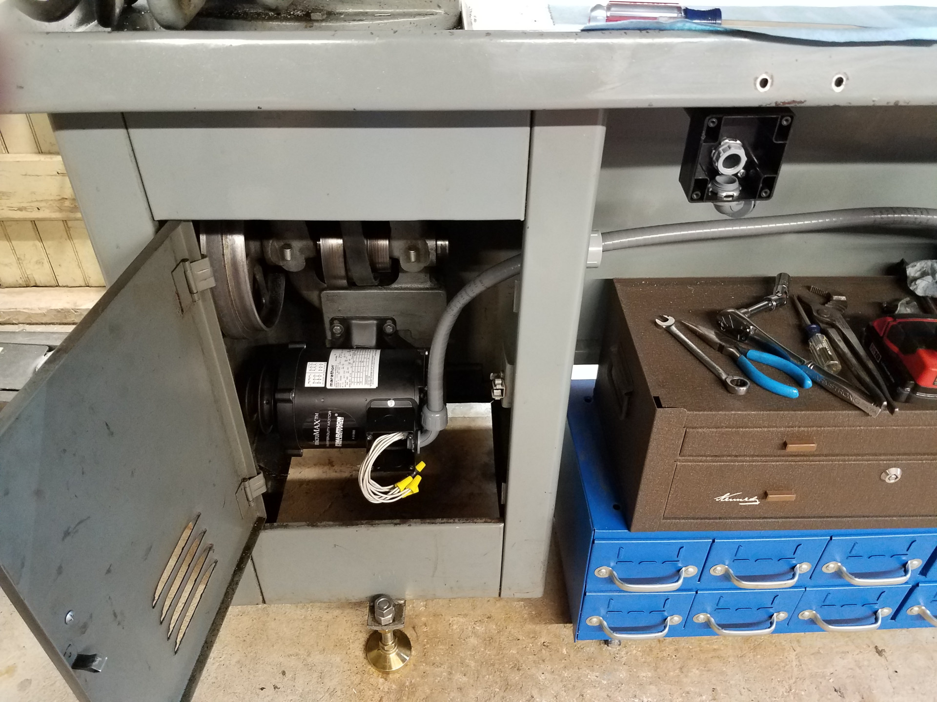
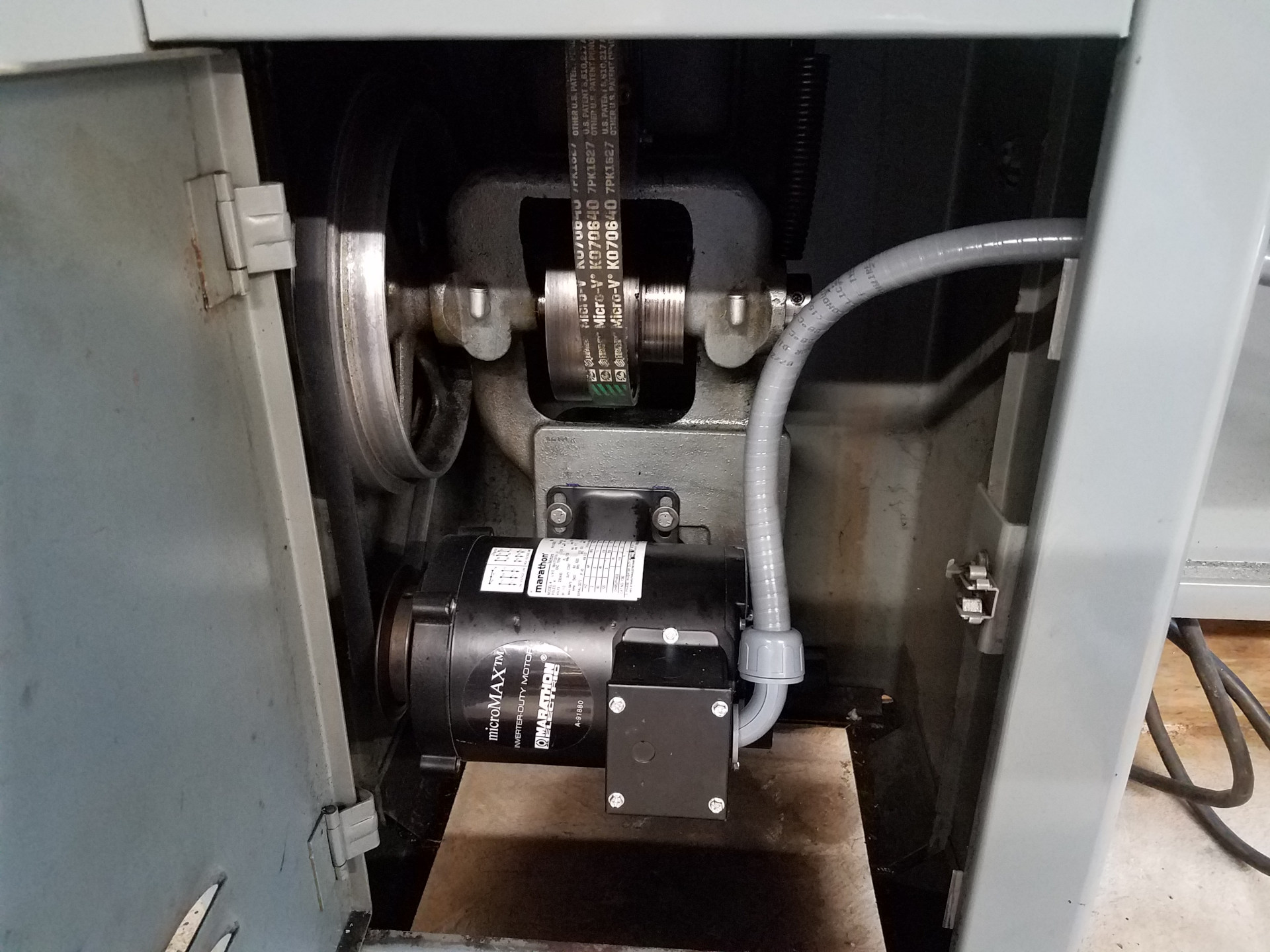
Here the motor is installed into the lathe and plumbed using water tight flexible conduit. South Bend thoughtfully provided a large knock-out plug in the cabinet which was used as a pass-thru for the flexible conduit. A PVC conduit adapter was used as a bushing though the cabinet so the flexible conduit doesn't catch on the sharp edges of the hole.
At the upper right you can see the emergency stop switch being mounted on the conduit used with the old drum switch.
Speaking about the VFD location, good spots on the lathe were limited so I decided to mount it at the same spot as the old drum switch. Back behind the tailstock would have been a location that worked, but that spot is already taken with the 6K collet rack. Space around the headstock is extremely tight because of the need to open the headstock and gear covers. I think putting control switches anywhere near the chuck is just plain stupid, so installing the VFD with the motor controls at the spot where I stand to use the lathe seemed the best option. I can say that after using this setup for over two years it has worked well for me.
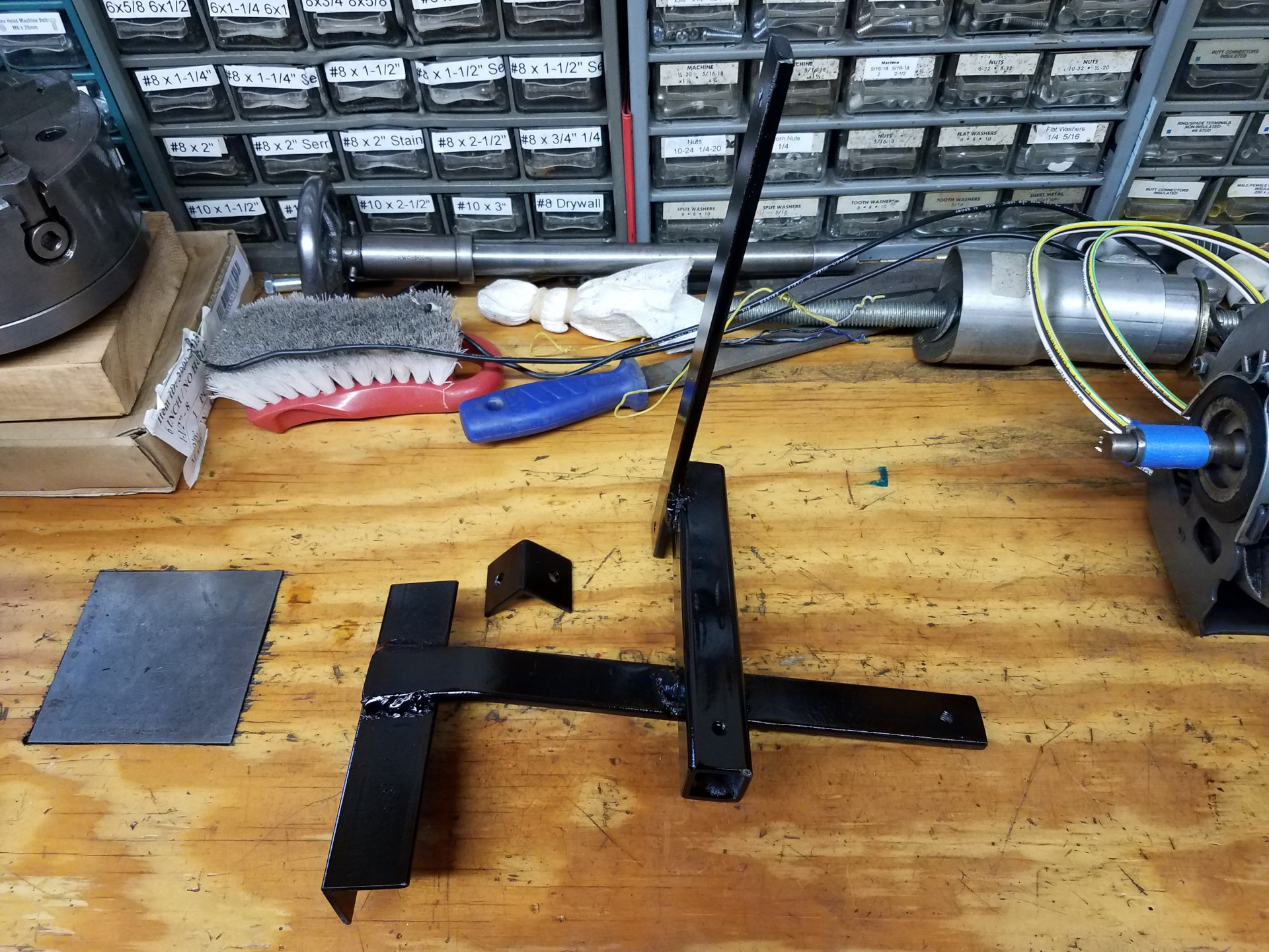
I didn't want to drill any unnecessary holes in the lathe cabinet so I devised this Rube Goldberg inspired mounting bracket to use existing holes in the cabinet to hold the VFD.
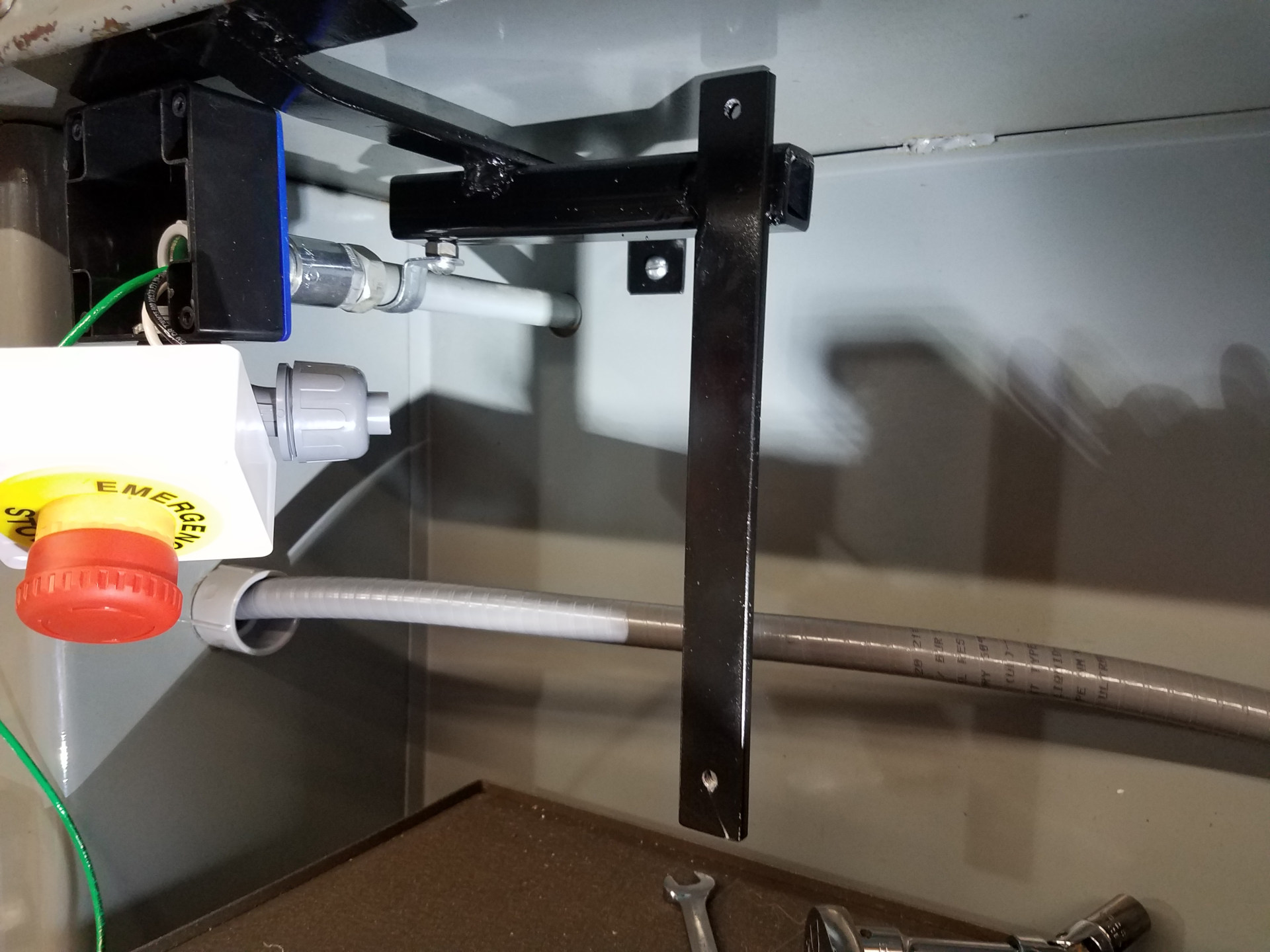
The VFD mounting bracket installed.
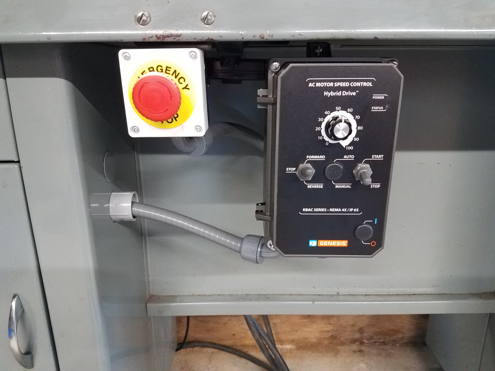
The emergency stop switch and VFD mounted and wired. The emergency stop switch cuts both hot and neutral (2NC) to the VFD, which I believe works the same way as the uninstalled factory switch at the bottom right of the VFD. This VFD has a setting that the motor will always be stopped at VFD power-up, so if the emergency stop is triggered when the lathe is running (killing power to the VFD) then when the power is restored the lathe will not immediately start running again even if the switch is in the run position. You will need to switch to start and then run. That switch has a spring-loaded start location at the top, run in the middle and then stop at the bottom.
Everything buttoned-up in the motor compartment. I wish it stayed this clean all the time!
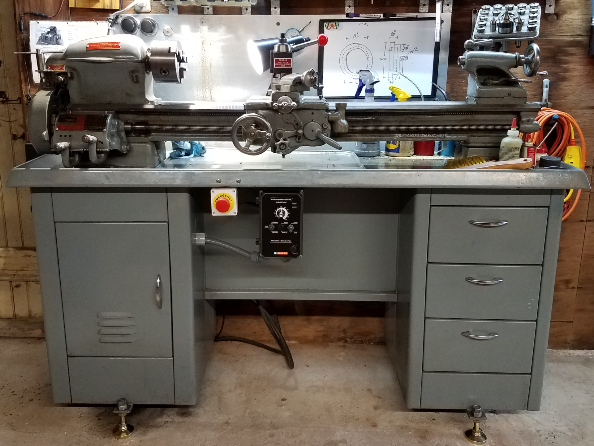
The completed VFD installation. This motor/VFD combination has worked flawlessly for several years now. The only critique I would offer for mounting the VFD in this location is that you have to reach down a bit to use the on/off switch but luckily this lathe is a bit higher with the tall floor mounts. One possible solution for reaching the on/off switch would have been to mount the VFD on it's side, although I'm used to the setup as it is and have no intention on changing it now.
Was it worth it? Absolutely! The old motor was occasionally giving me trouble because of oil entering the workings, so an upgrade was soon needed. The variable speed feature of the VFD drastically cut down on moving the belt for speed settings and offered a new range of higher speeds that were not available with the single-speed motor. The low speeds provided by the VFD has meant back gears are rarely used for single point threading, but they are still handy for drilling large holes with tailstock mounted drills. Even at low speeds under load the motor can still turn the chuck, but the flat belt will tend to slip without using back gears.