The float lock drill press vise build concludes with this article. In this build I got a chance to experiment with some single point ACME threading on the lathe while turning between centers. After the vise body was completed, the second major part of the build, which was devising a way to fasten the vise onto the drill press table in a clean and usable fashion, took almost as long to complete as the vise itself.
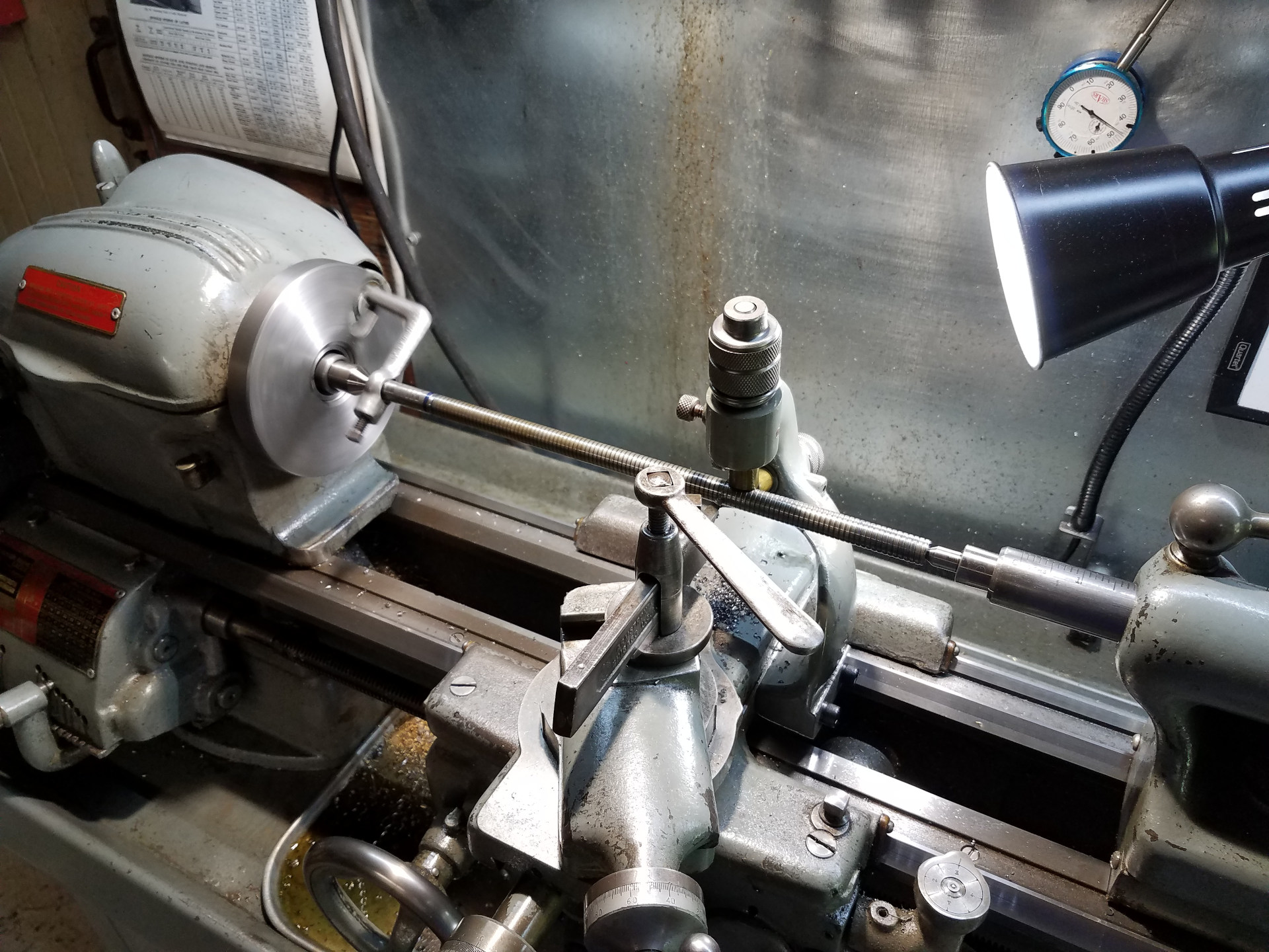
Here the lathe is used to produce the ACME threaded rod via the single point method while holding the work between centers. Since cutting an ACME thread is somewhat aggressive, the follow rest was used to reduce the chance of chatter. It's difficult to use this lathe's follow rest with an Aloris-type QCTP, so the old lantern style tool post that originally shipped with the lathe was brought out of storage and used for this operation. The toolbit was custom ground to the ACME profile from a piece of 1/4" HSS.
One of the advantages of turning between centers is that it's easy to remove the work from the lathe for a test fit and return it without any chance of losing concentricity.
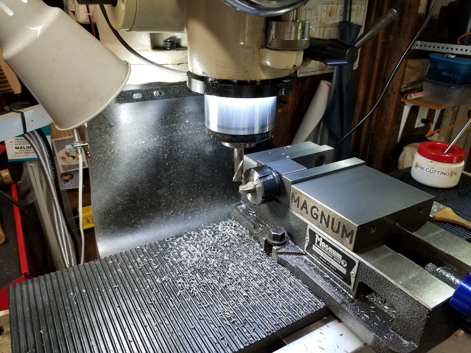
A collet block is used to hold a piece that is part of the vise handle swivel.
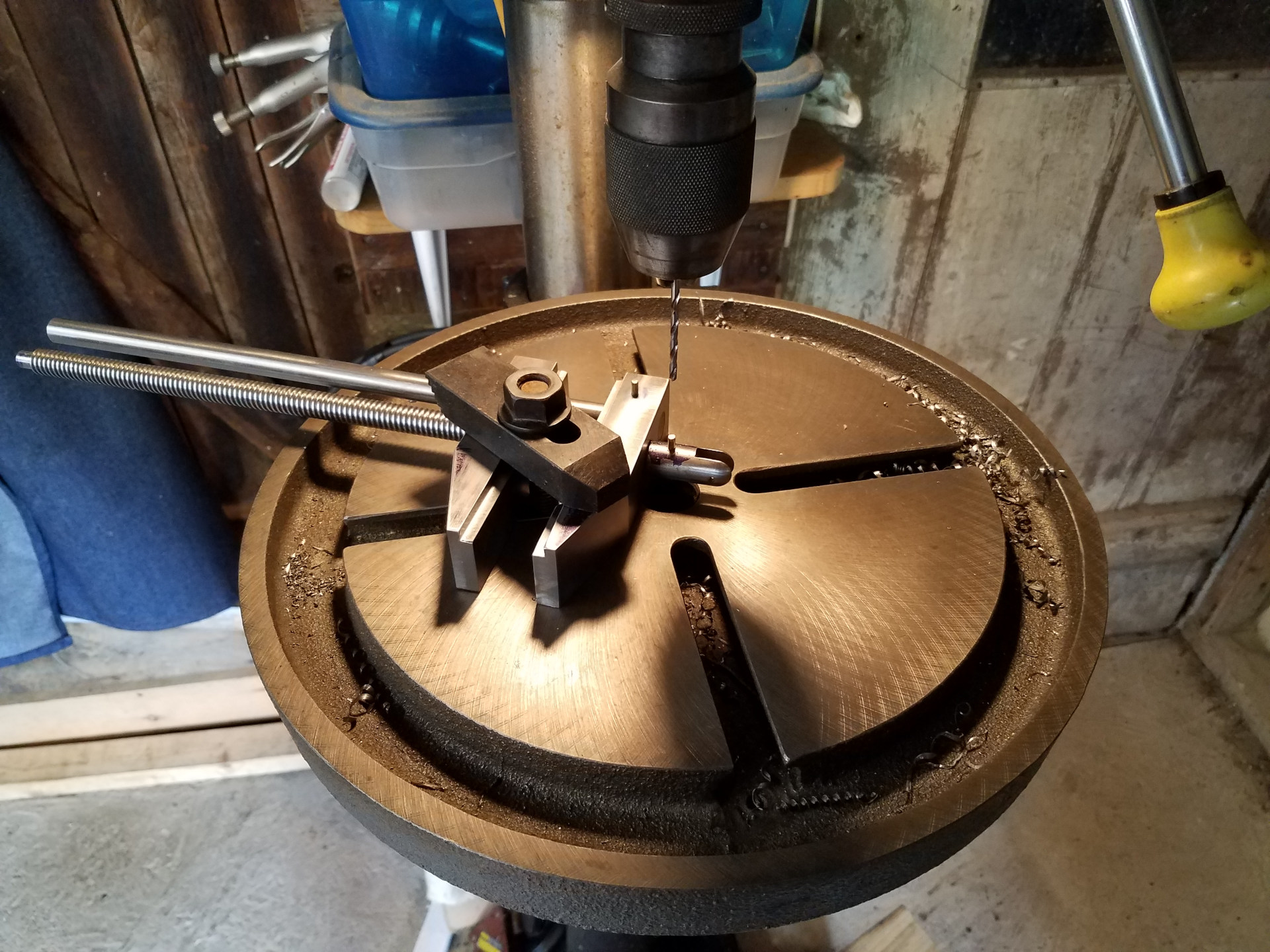
Using the drill press to drill the pin hole through the threaded rod for the swivel piece.
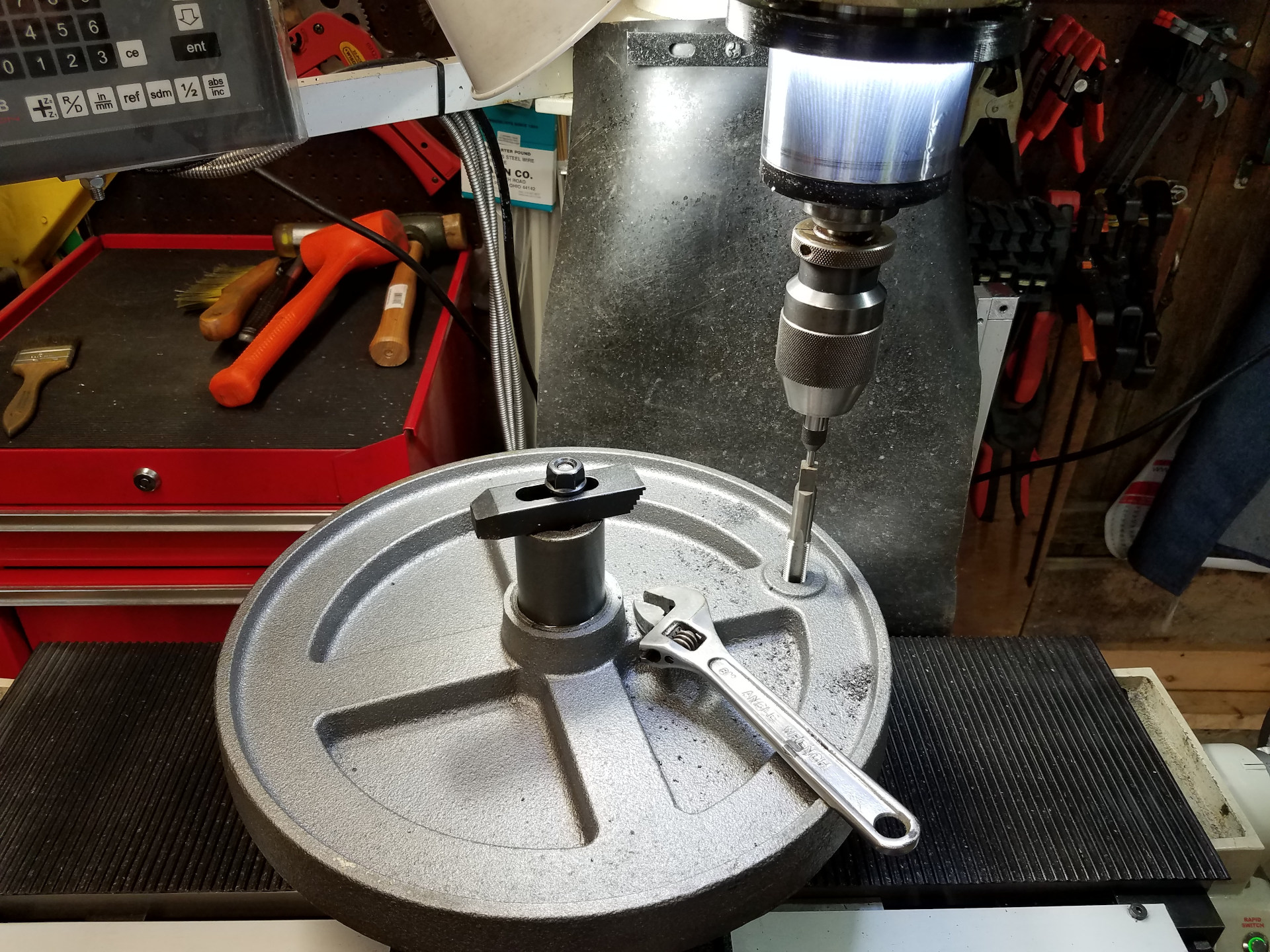
This drill press has an unusual slotted, round table making it difficult to mount the float lock vise which is usually mounted in a table corner. The drill press also shipped with an odd gravity-fed liquid cooling system which used two bottles in which the bottom bottle was fed from a hole in the table. While the bottle cooling system was never used, it did provide a nice mounting hole in the table for the vise mounting bracket. Here the hole was drilled for tapping in the next nominal size and tapped as shown.
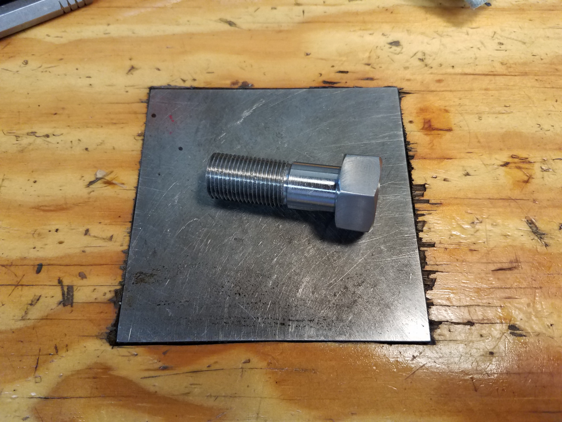
The mounting bracket bolt was made to fit the tapped hole in the table. When you have a QCGB for the lathe and a hex collet block for the mill, many times it's quicker to make one bolt in the shop. This is especially true for an off-size, as you might make a trip to the store and not find what you need.
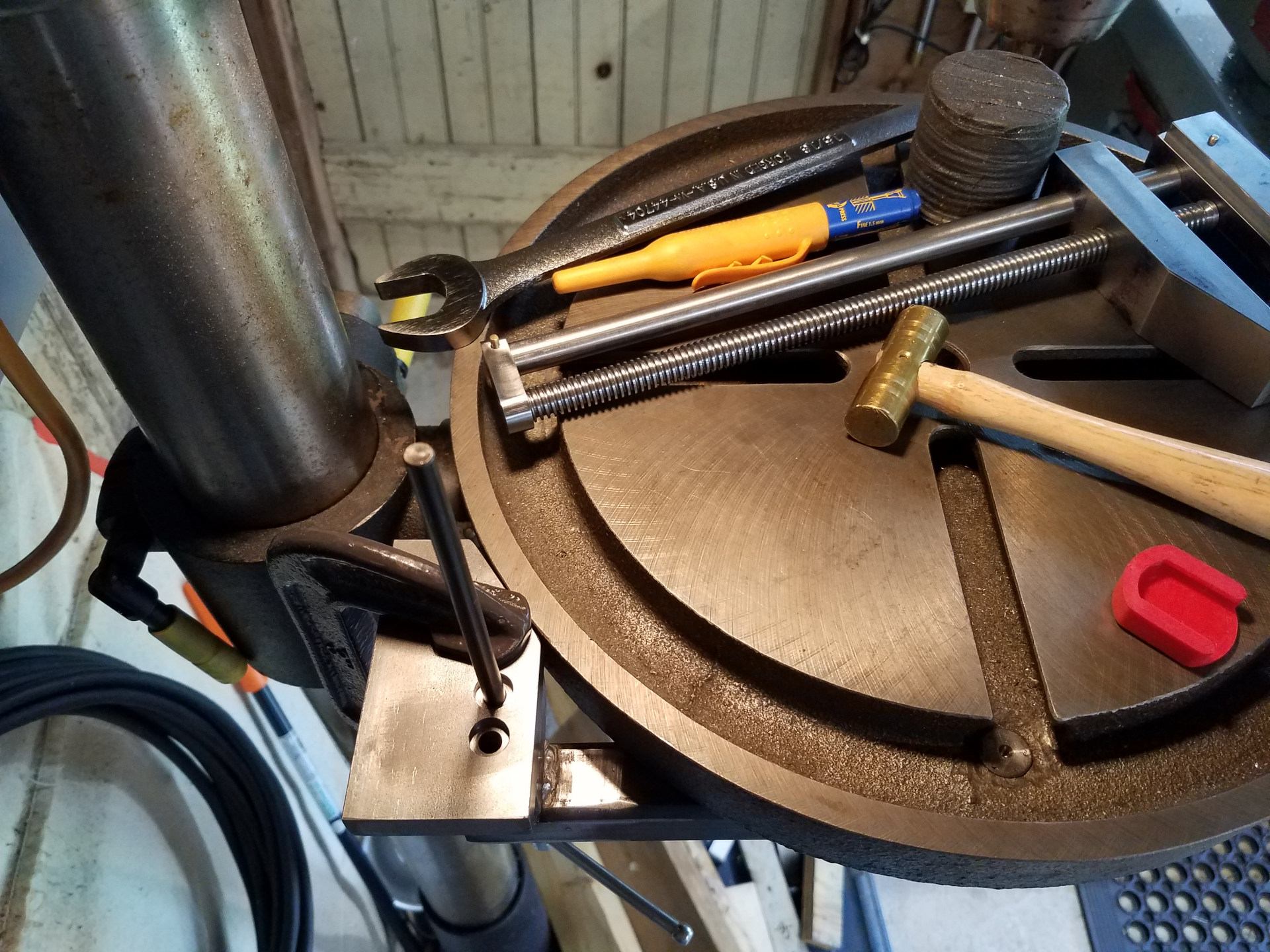
One inch square tubing was used to fabricate part of the mount for the vise. Here the mounting plate holes are transferred to the tubing to be drilled and tapped.
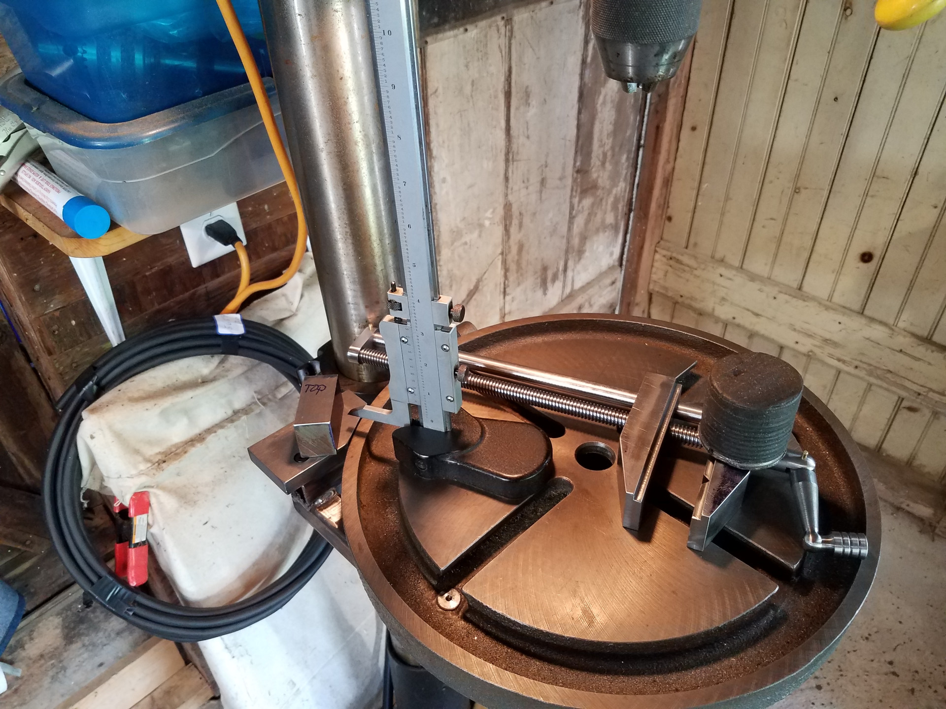
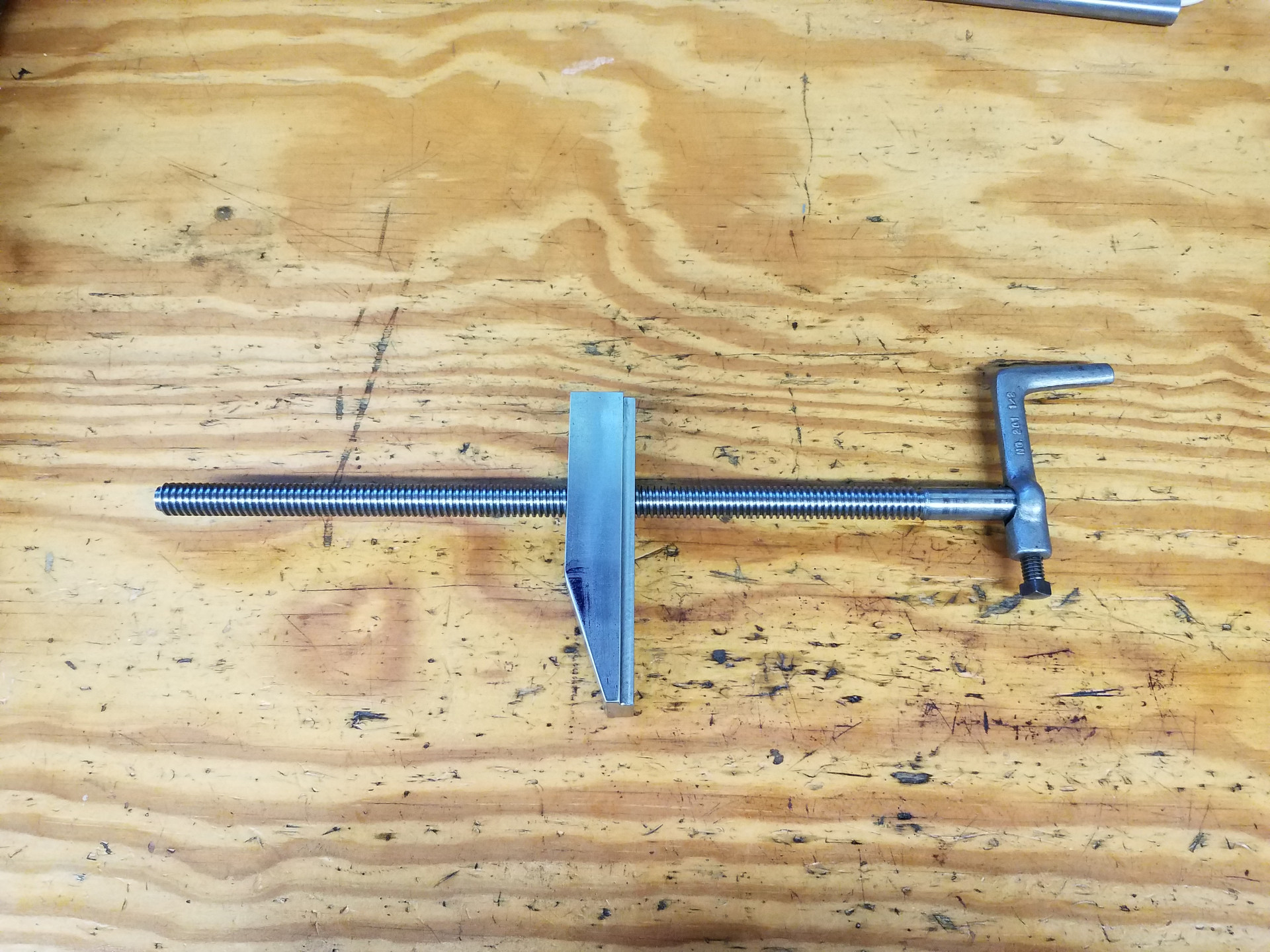
The clamp block is being marked for the split lines. You want to make sure the split line is in the correct spot so the vise doesn't float above the table when locked in place.
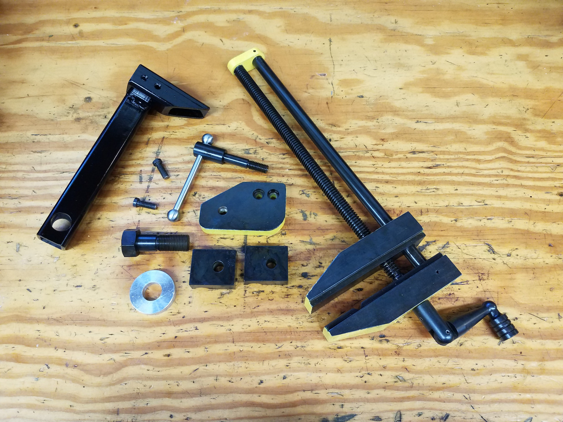
The completed vise parts after painting and bluing. On the left is the fabricated mounting bracket made from square tubing. It's held to the table with just that one large bolt which has proven to be rigid enough.
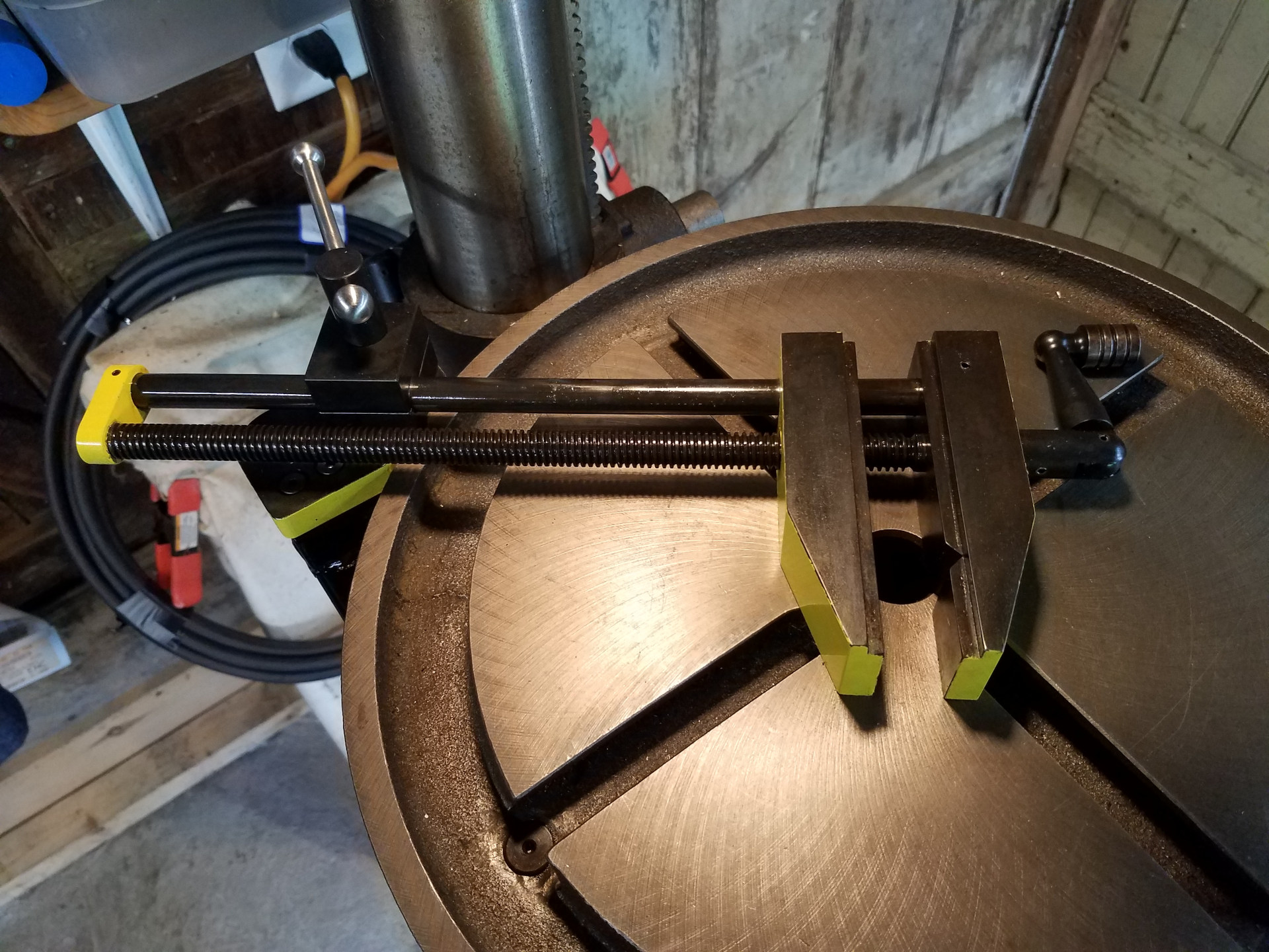
The finished float lock vise installed on the drill press.
A short video showing the operation of the float lock vise. Clamped in the vise is a plate with two dimples to mark the spots for two holes. Here I'm letting the work find it's center in that dimple with a running drill. When that's found, turning the vise locking lever locks the vise in place and the work is drilled as normal without worry.
The float lock drill press vise has proven itself to be a great asset for the drill press. It allows you to work quicker and safer at the drill press because the vise is always available and ready to use. If the entire drill press table is needed for an operation, the vise can easily be moved out of the way.
Having used the vise for awhile now, the only thing I would change would be to make both the threaded and plain rod a few inches longer as it's easier to tighten the work in the vise with the handle off the end of the table. This hasn't been a big enough issue, however, to make me want to remake those two parts,