After the VFD installation, sometimes when using the lathe I wished for a tach to keep track of the spindle RPM's while adjusting the variable speed control. While not completely necessary, it is sometimes convenient to have an accurate gauge of spindle speed than just a guess by the sound of the lathe and location of the drive belts. Luckily, digital tachs using a hall effect sensor are accurate, cheap and relatively easy to install as shown in this article.
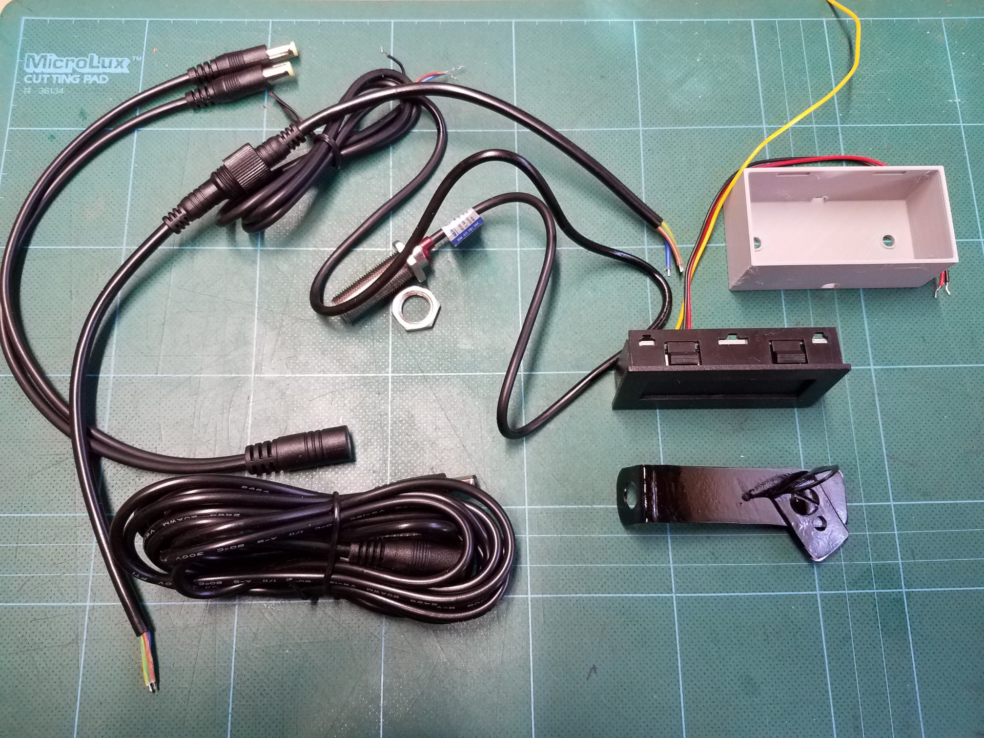
All the items needed for the digital tach installation.
The tach display with hall effect sensor was inexpensive at under $20. The gray enclosure for the LED display was 3D printed from a file downloaded here:
https://www.thingiverse.com/thing:2170657
The device is powered from the same 12V DC source that is used to power the under shelf LED lighting installed directly above the lathe. A Y-adapter and additional power cables were obtained to allow an easy connection to this existing power source.
A multi-conductor water-proof connector with bare wire ends was sourced for the wire between sensor and LED display. Since the display will be mounted on the shop wall, I wanted a quick and reliable way to disconnect the sensor wire from the display if the lathe needs to be moved for some reason.
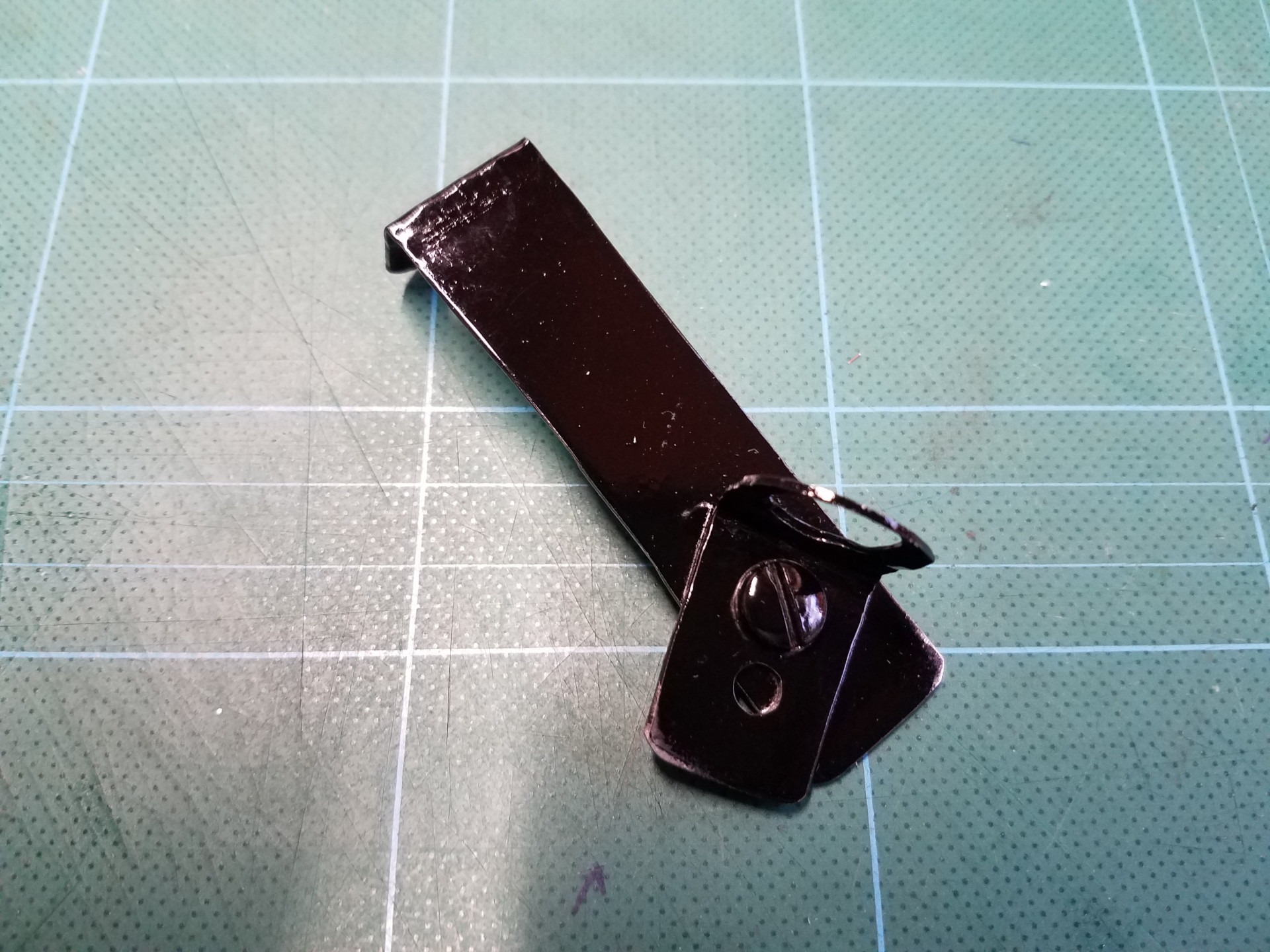
A shop-made bracket to hold the hall effect sensor. It was quite challenging to find a good spot to mount the sensor so it will measure the spindle speed and still not get in the way.
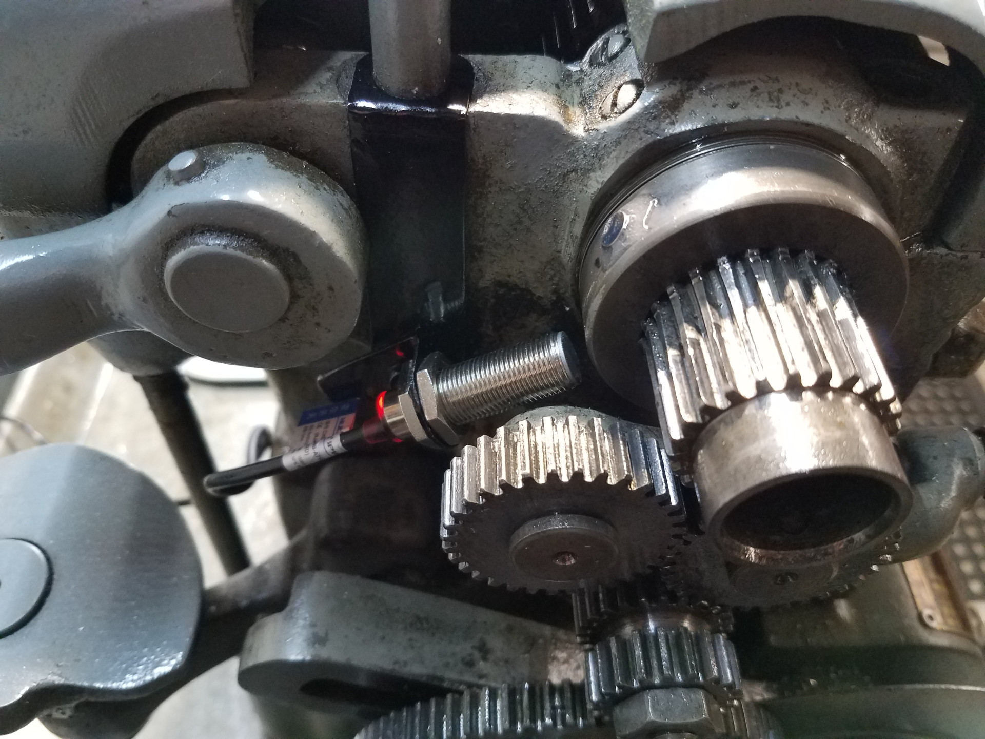
Here the hall effect sensor is mounted on the lathe and the magnet the sensor detects is epoxied to the spindle take-up collar. Everything works as it should, but as you can see mounting space is at a premium. The sensor bracket is attached to the lathe frame by the mounting screw for the lever type collet closer which I don't own nor will ever use.
For the last few years the magnet has stayed attached to the collar but it would be a Bad Day if it fell off and ended-up in the gears. It's wise to inspect the epoxy joint on a regular basis.
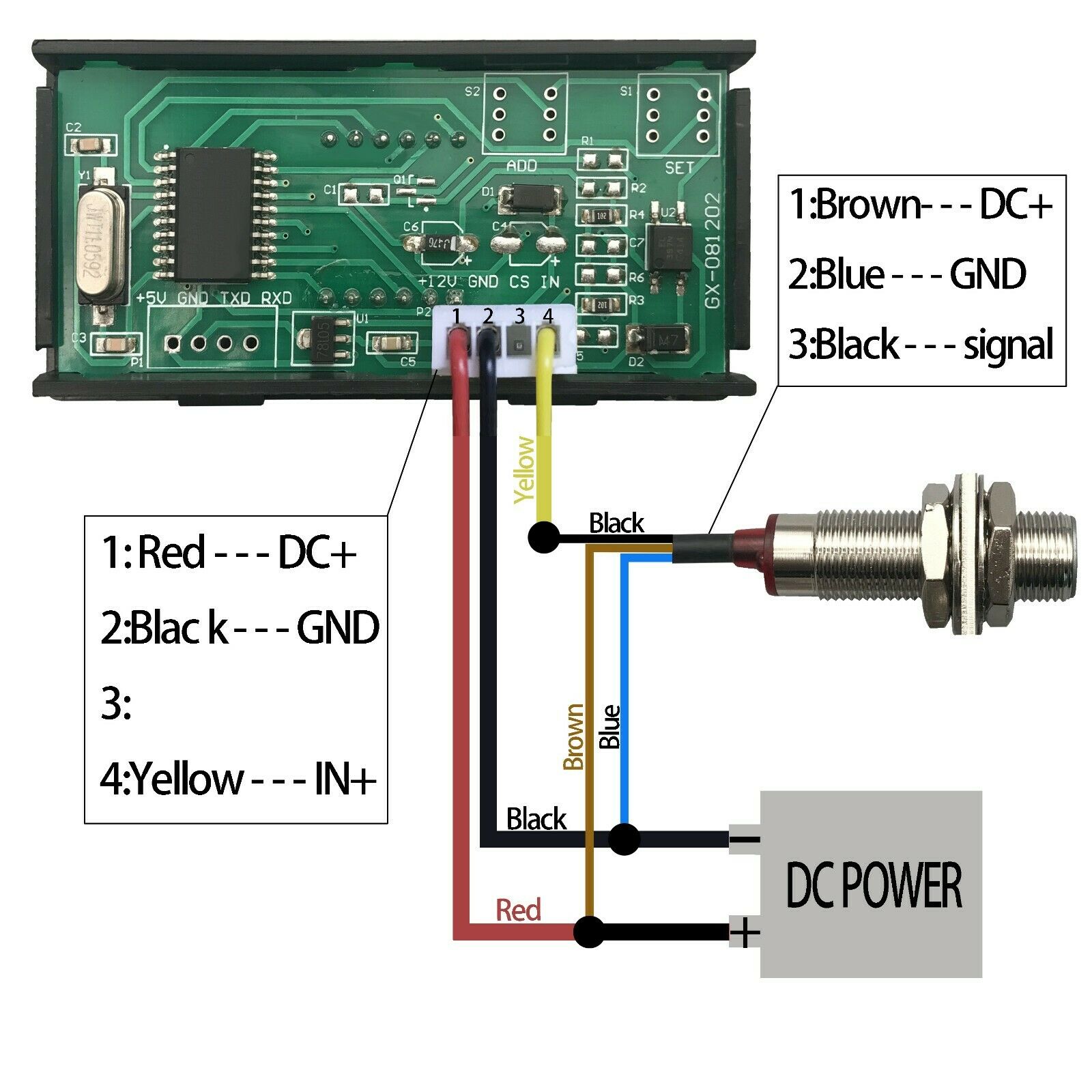
This is the wire schematic included with the hall effect tach package that I used. The DC voltage supplied to the unit should be 8-15V.
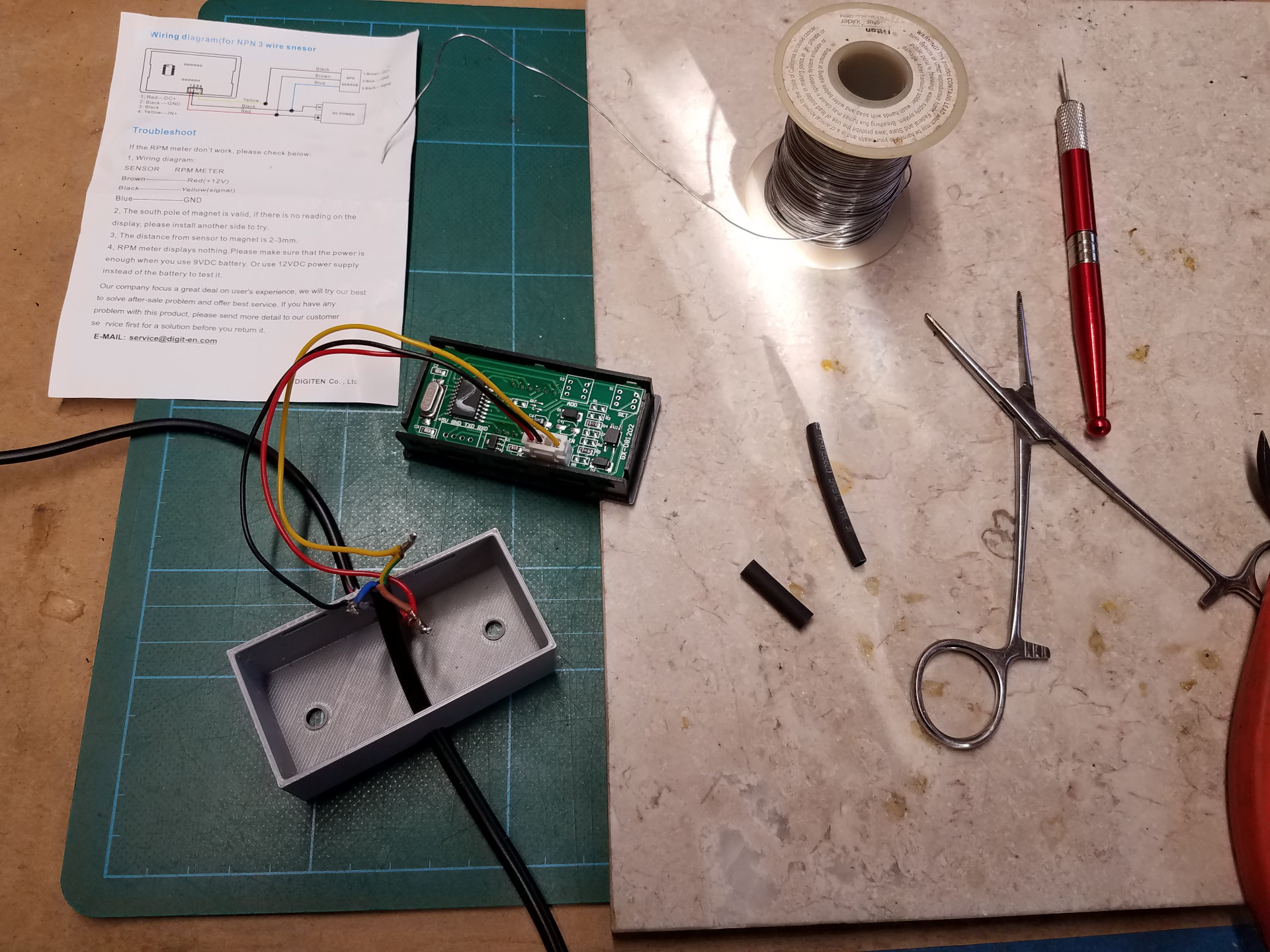
Getting all the wires soldered together.
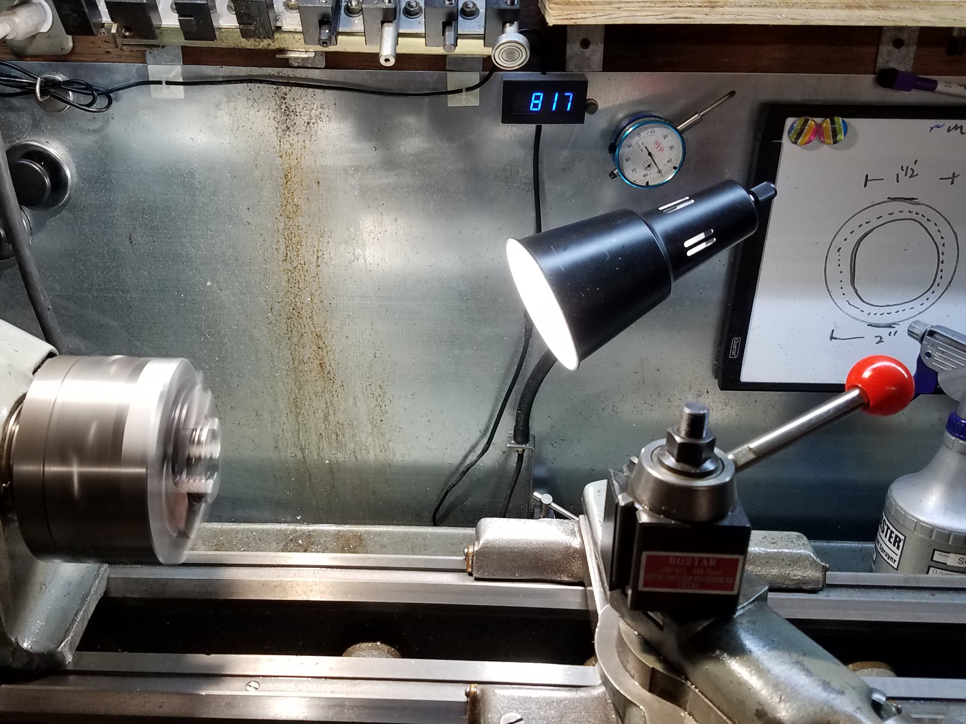
The digital tach installed and working.
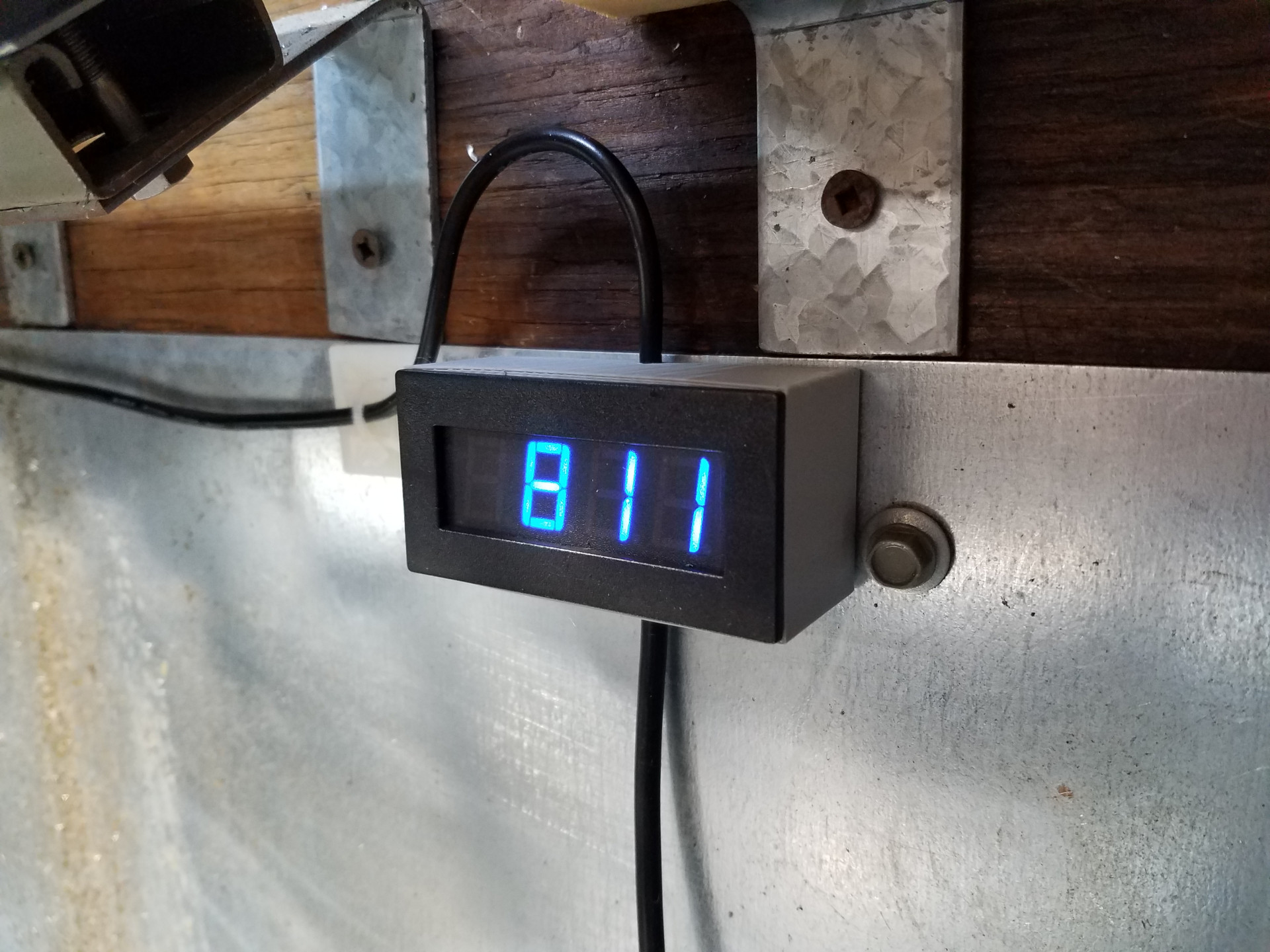
Close-up of the display. The display is bright, clear and easy to read.
Installing the tach was a quick weekend project and allows the lathe operator a bit more information when selecting and adjusting spindle speeds. It compares well to a hand-held laser tach and it's been working flawlessly for the last couple of years. The only minor complaint I have with the tach is that it's slow to update, but for lathe use this isn't really a big issue.