Several future projects in the work queue will need some shop made gears. Almost all the necessary tooling for gear making is already in the shop and I would like to make a gear now to help streamline the process for making future gears. Since I already have a set of the proper involute gear cutters for the lathe's change gears, I'll start with making a gear that will allow single-point threading on the lathe a thread TPI that is not available as a selection with the lathe's QCGB.
This is a good video series on how to cut a gear on the mill. Mr Pete goes over much of what I'm doing here and clearly explains gear cutting nomenclature, how to select the proper cutter, gear blank size, etc. Highly recommended viewing!
First the gear blank was cut from bar stock with the bandsaw and both sides faced-off on the lathe. It's a shiny, hard metal, probably 1018.
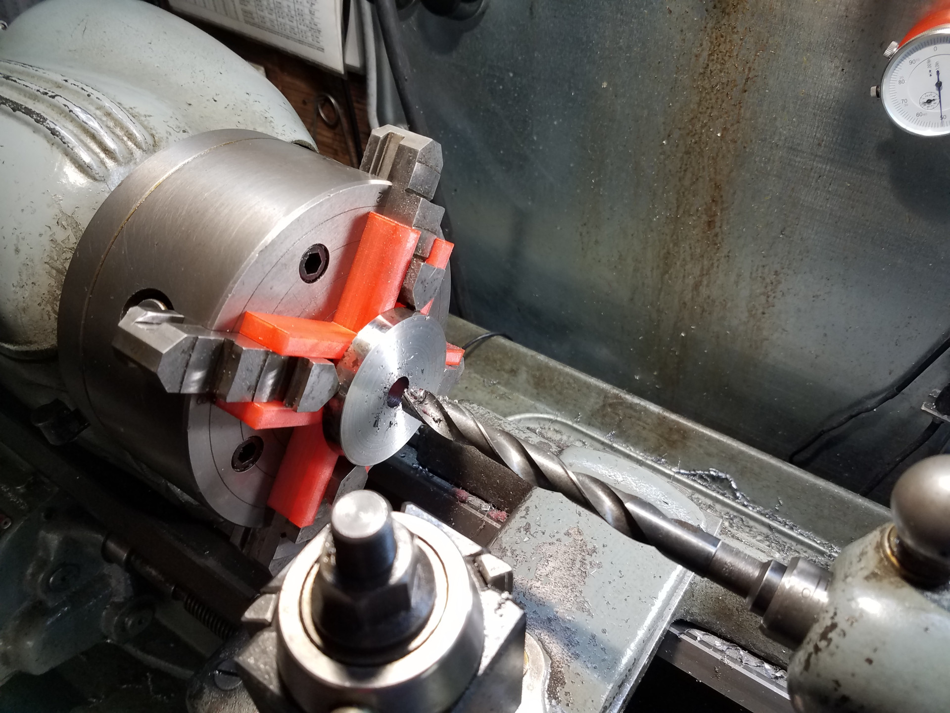
A hole is drilled in the blank.
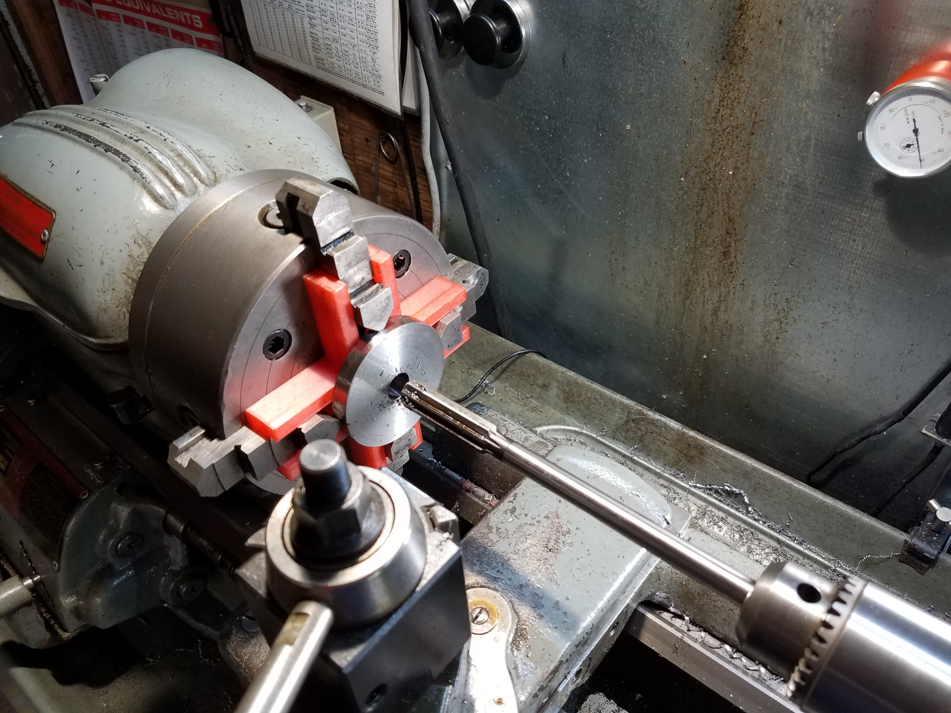
And then reamed to the correct size.
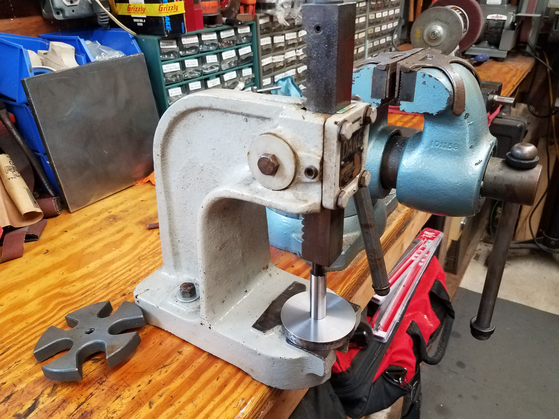
A specific lathe arbor was bought for this project. Since I made three blanks and ended-up with two gears, it was a timesaver using the arbor and a recommended purchase. Here the little Dake press is used to press the arbor into the blank.
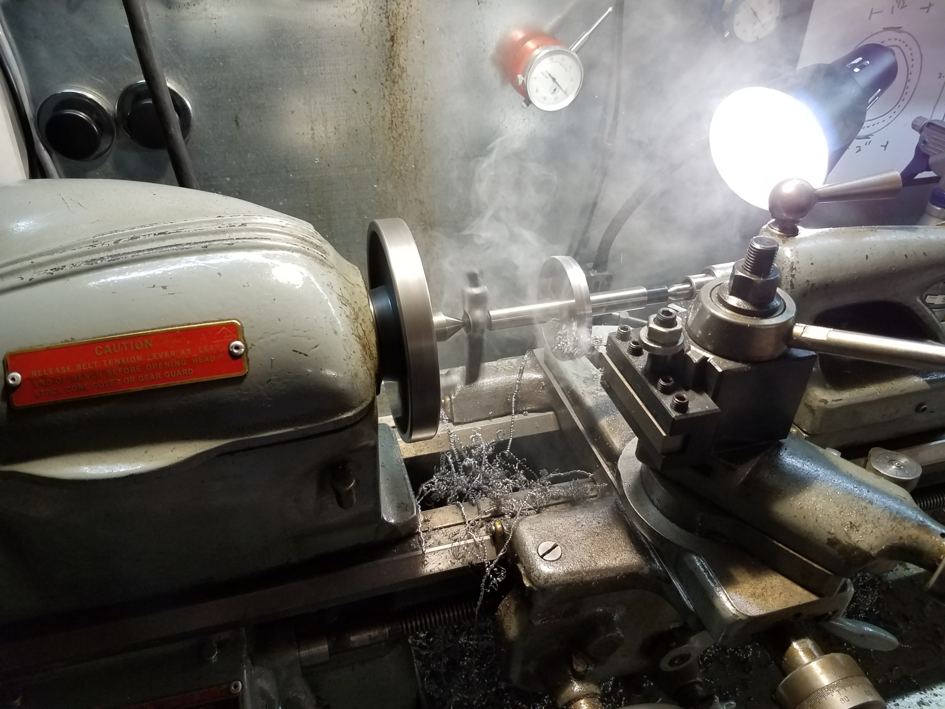
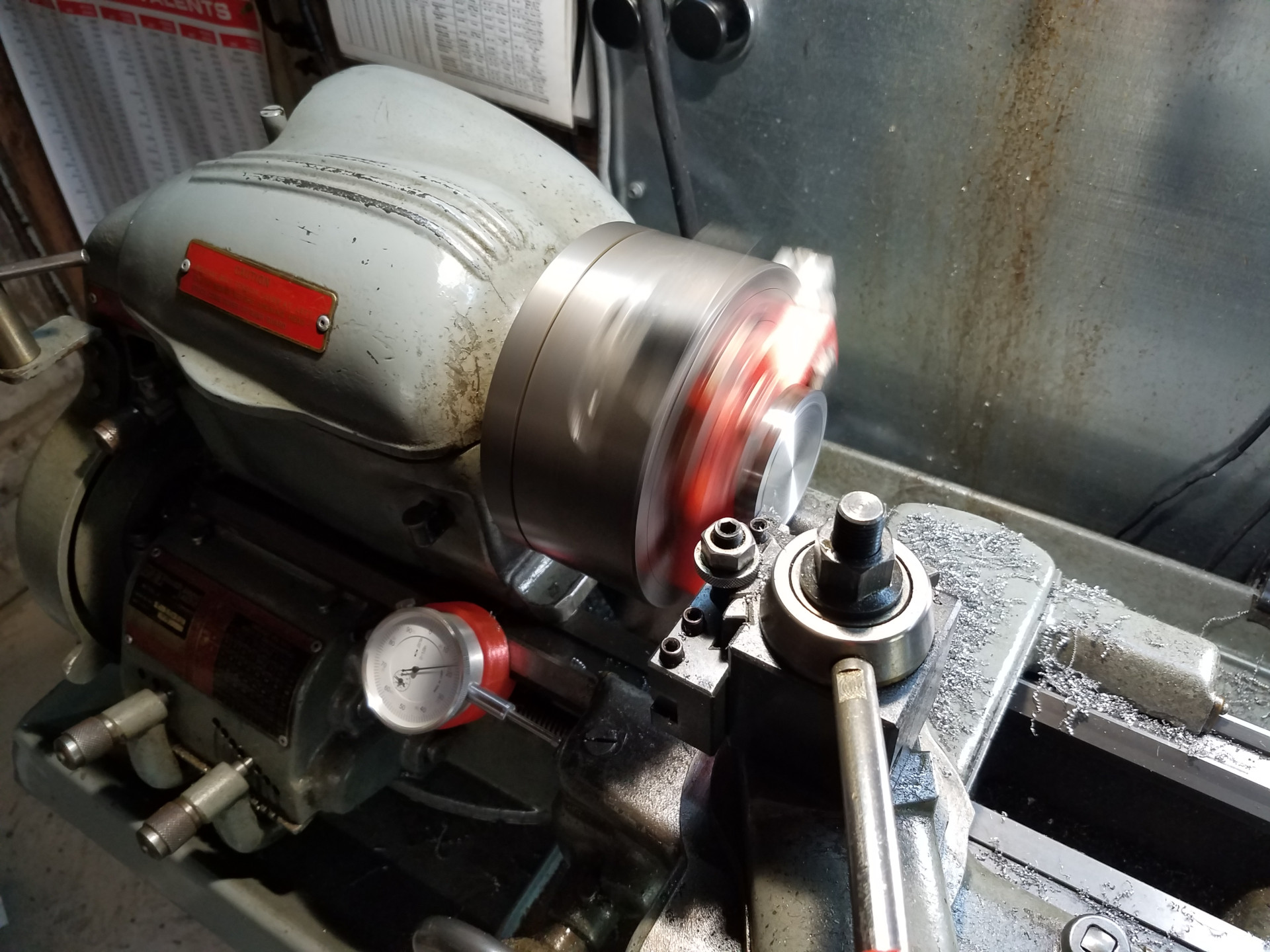
The outside of the gear blank is turned on the lathe to the correct diameter by turning between centers while the arbor is driven by a lathe dog. A very old-school way of doing things and still a great way of maintaining concentricity when you need to move parts between machines.
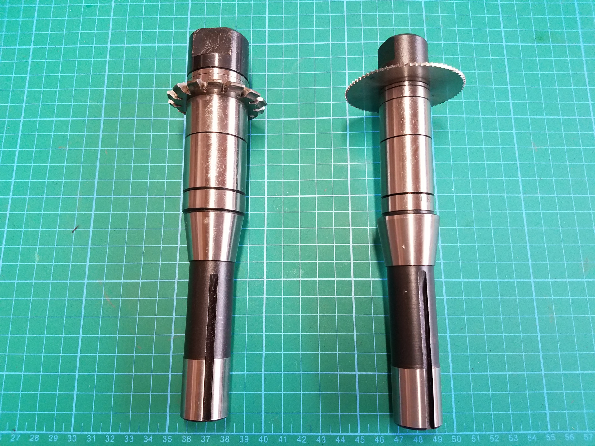
These are the two cutting tools that will be used at the mill, both mounted on R8 arbors (two different sizes). The slitting saw on the right will be used for the initial roughing cut and then the involute gear cutter on the left will complete the tooth profile in one pass. The gear profile needed is 18 diametral pitch, 14 1/2 pressure angle. For a 42 tooth gear, cutter #3 from the set is needed.
Not sure if the roughing cut is necessary, but it does help save some wear on the gear cutter, keeping in mind it's a very inexpensive import.
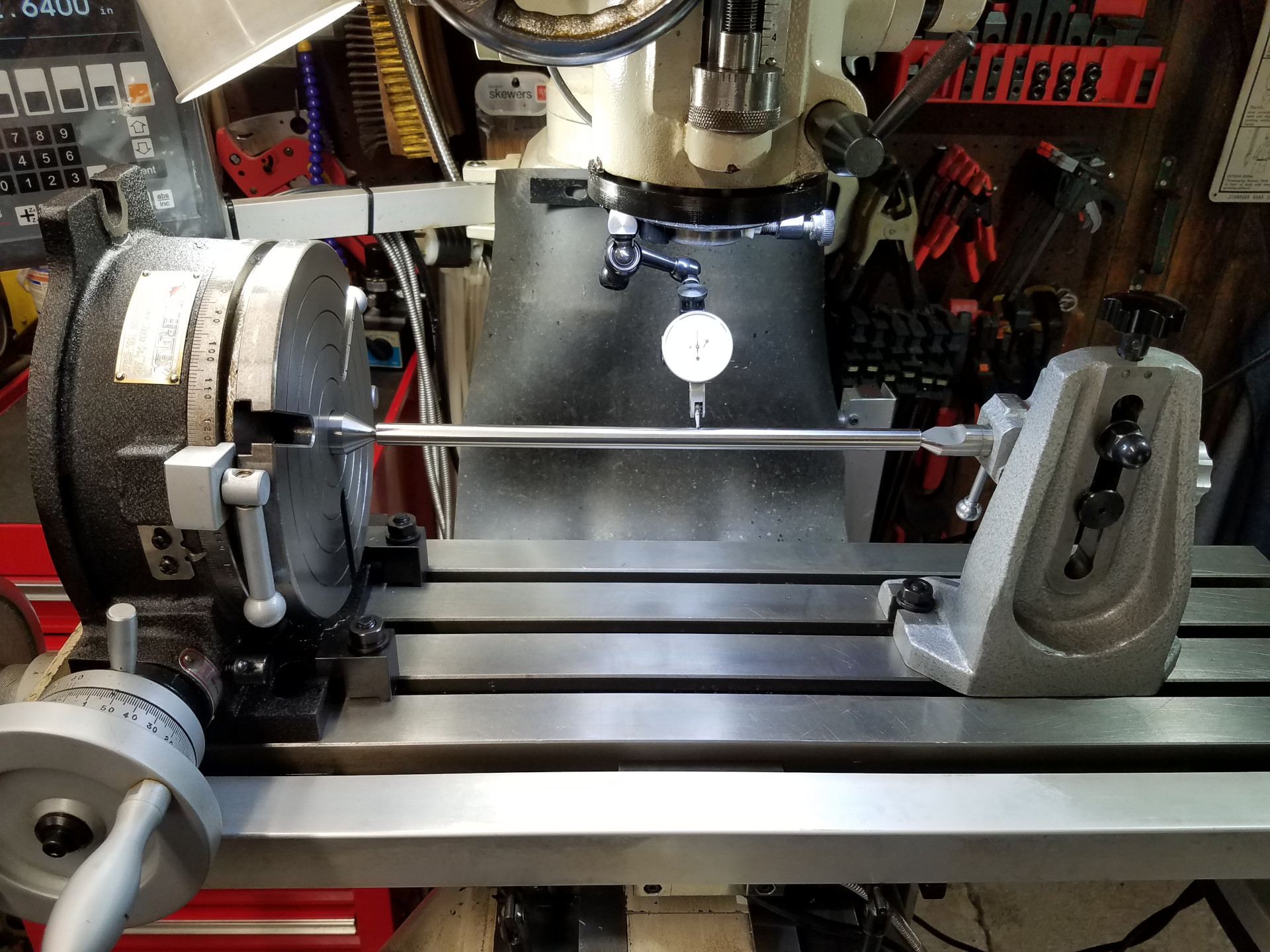
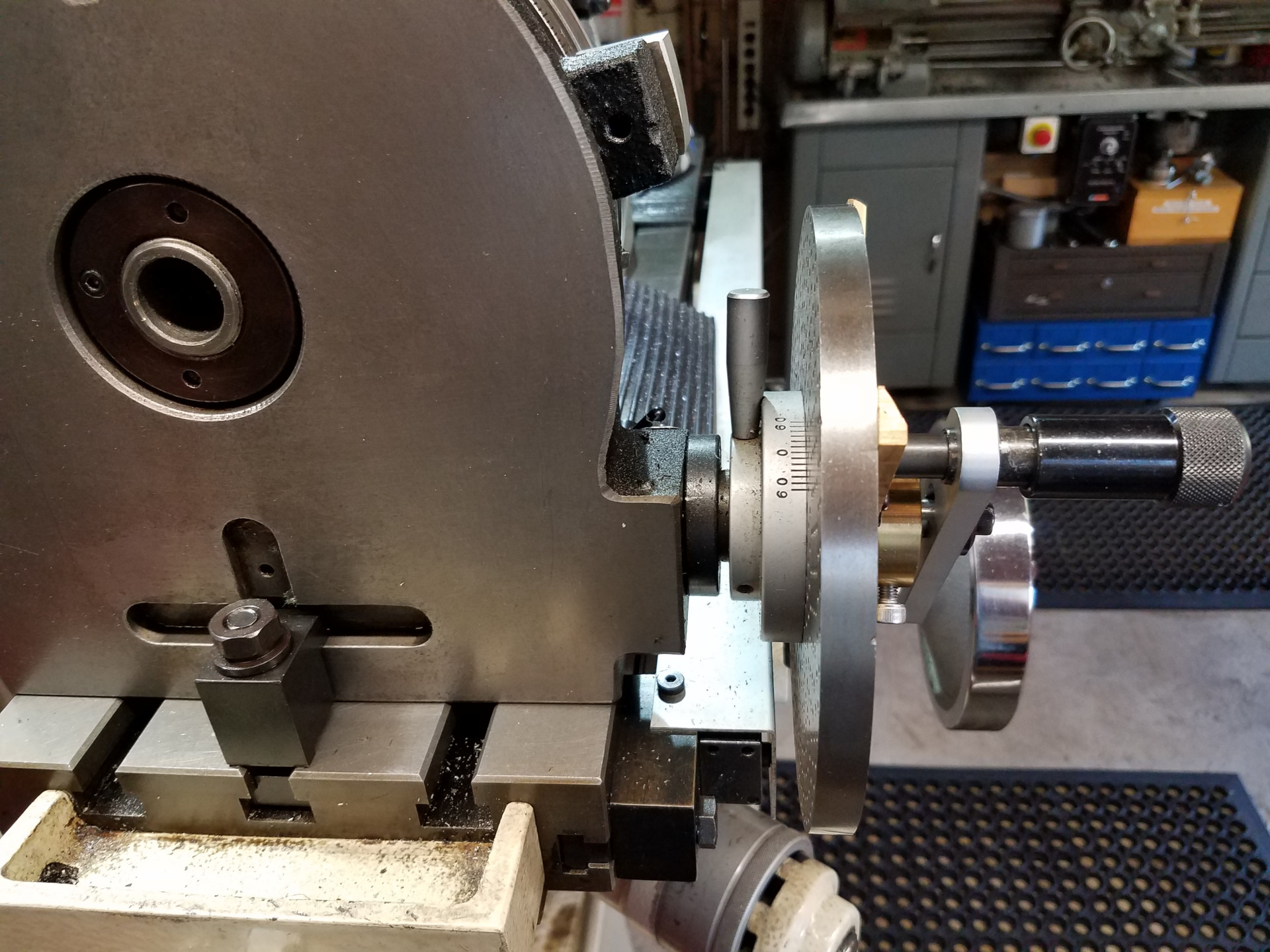
Checking the alignment between the rotary table and the tail stock with a test bar. The tail stock uses alignment keys in the base that work off the table slots, so the bar mostly checks that the rotary table is in the correct spot perpendicular to the bar and that the tail stock is at the correct height.
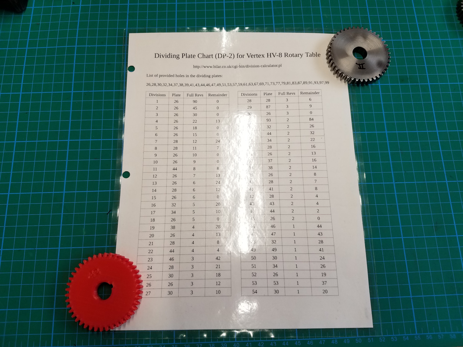
I'll be using the dividing plates with the rotary table. In this case I'm making a 42 tooth gear, so I'll need the plate with 28 holes for the 42 divisions.
I keep this handy laminated sheet of all the rotary table's available divisions in the shop. This double-sided sheet was created from information generated at this website:
http://www.bilar.co.uk/cgi-bin/division-calculator.pl
A typical dividing head has a 40:1 gear ratio, whereas most rotary tables, this one included, has a 90:1 gear ratio. For gear cutting, this means you end up turning the table more revolutions per increment than a 40:1 dividing head. On the other hand, with the rotary's table wider gear ratio there seems to be less unavailable divisions compared to a regular dividing head. A classic example is the 80/63 metric transposing gear, where 63 divisions are not available with a standard 40:1 dividing head but are available with this rotary table.
When you are planning on adding DRO scales to your mill, make sure everything will fit before you commit. I knew that the rotary table's dividing plates would offer the least amount of clearance and designed the mill's X scale setup to work within that confined space.
The gear cutting will continue in the next article.