The gear creation project continues with indicating the blank to run true, setting the cutter height, cutter depth and finally cutting the blank with an involute gear cutter. After the blank is deburred, the gear is inspected with the two wire method and a recommended web page with gear information is shown. After that, the gear keyway is cut with a broach and another way of making gears is shown.
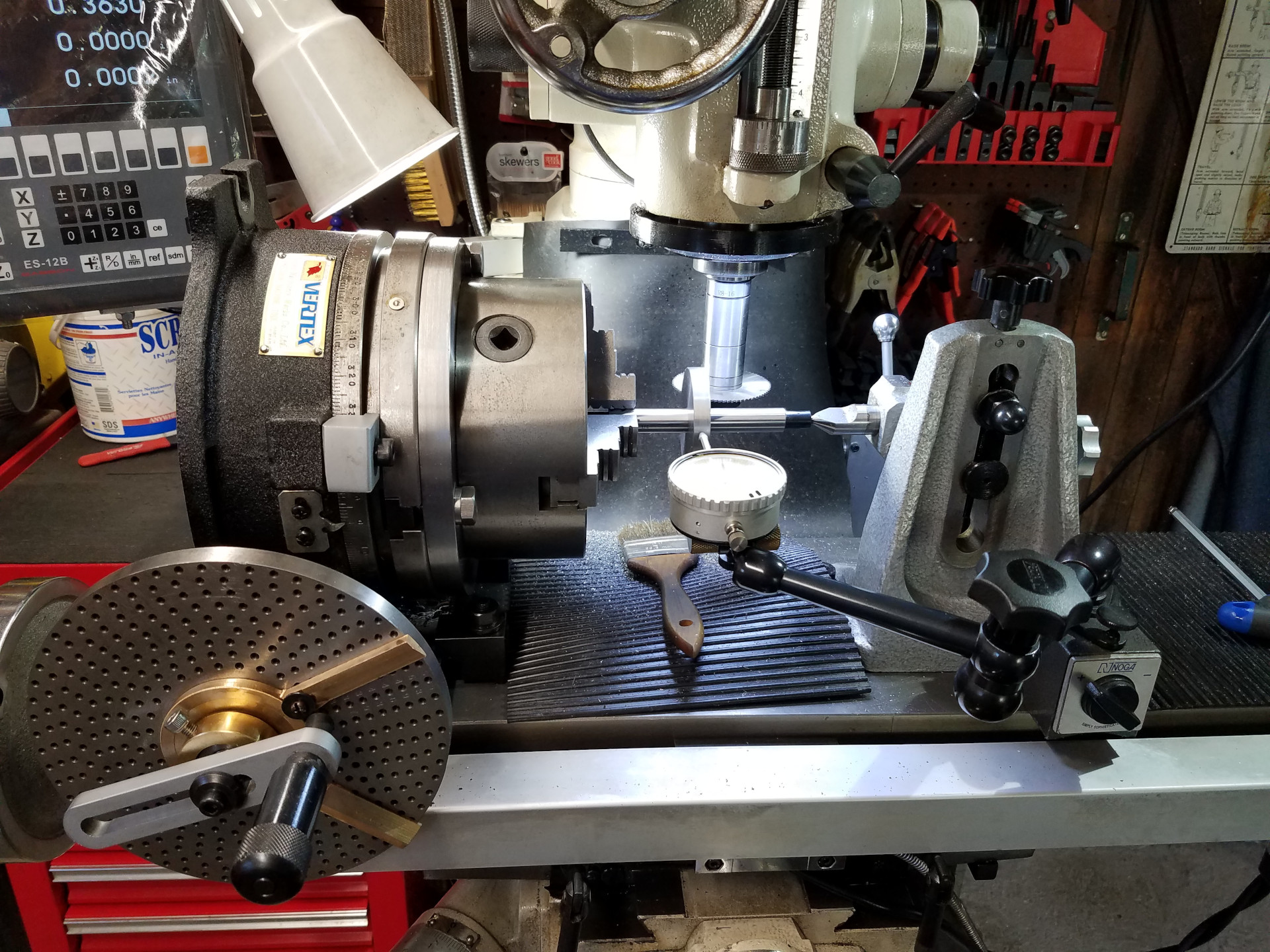
I'm now using a chuck with the rotary table because I believe it will hold the arbor better and produce less chatter than holding the arbor between centers and turning it with a drive dog. Here I'm indicating off the gear blank and with slightly loosened chuck mounting bolts the chuck is bumped true for no indicated run out.
The cutter height is set with the aid of a piece of HSS clamped to the top of the slitting saw as the saw isn't wide enough to reach the top of the arbor. The HSS was touched-off to the top of the arbor, then the DRO was zeroed and the process was repeated at the bottom of the arbor with the HSS clamped to the bottom of the saw. Using the half-function of the DRO will find the center of the work for the correct cutter height.
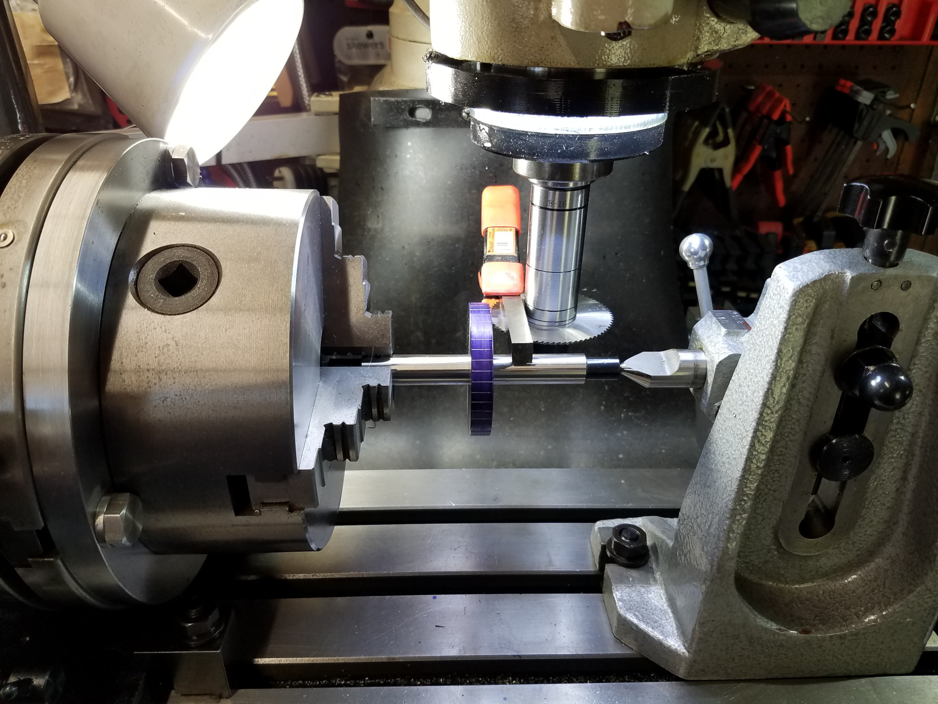
First the gear blank is gashed with the slitting saw for a roughing cut at each tooth interval. This is mainly to save wear and tear on the expensive gear cutter.
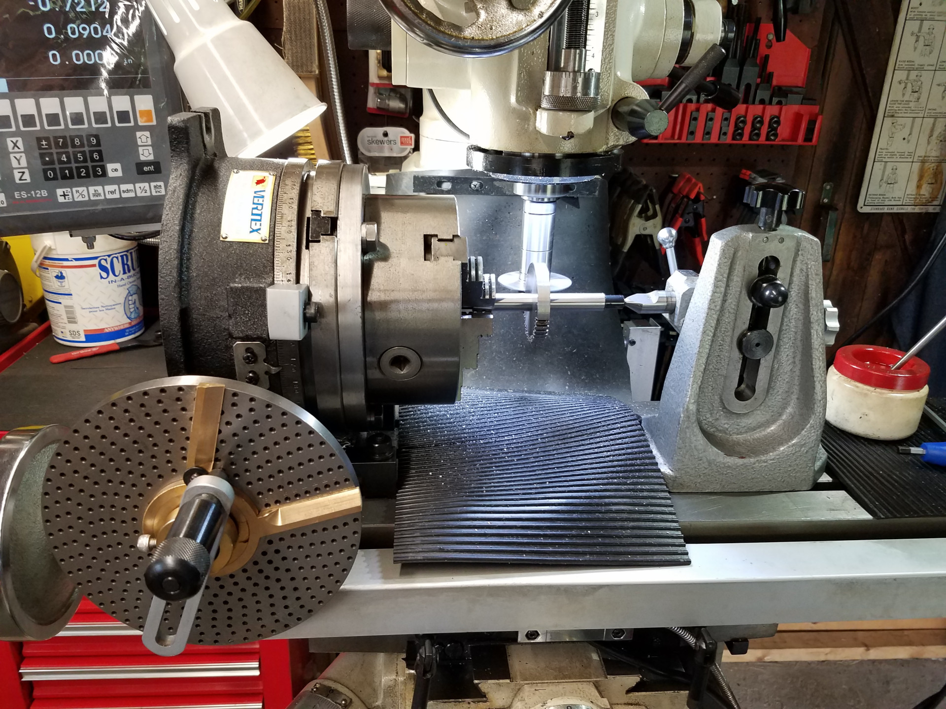
The slitting saw arbor was removed from the mill and replaced with the arbor with the involute cutter installed. The height of the cutter was set using the same procedure as mentioned before. A feeler gauge is used to bridge the slitting saw cuts for touching-off the gear cutter against the gear blank. After that, the cutter is moved towards the work the thickness of the feeler gauge and then to the depth of the gear tooth.
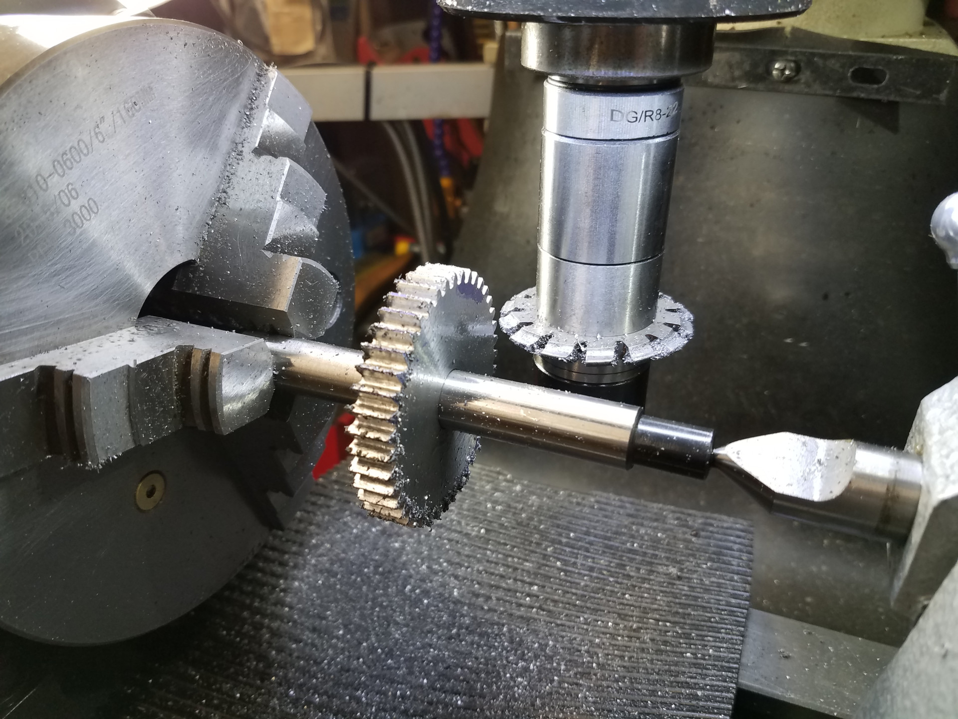
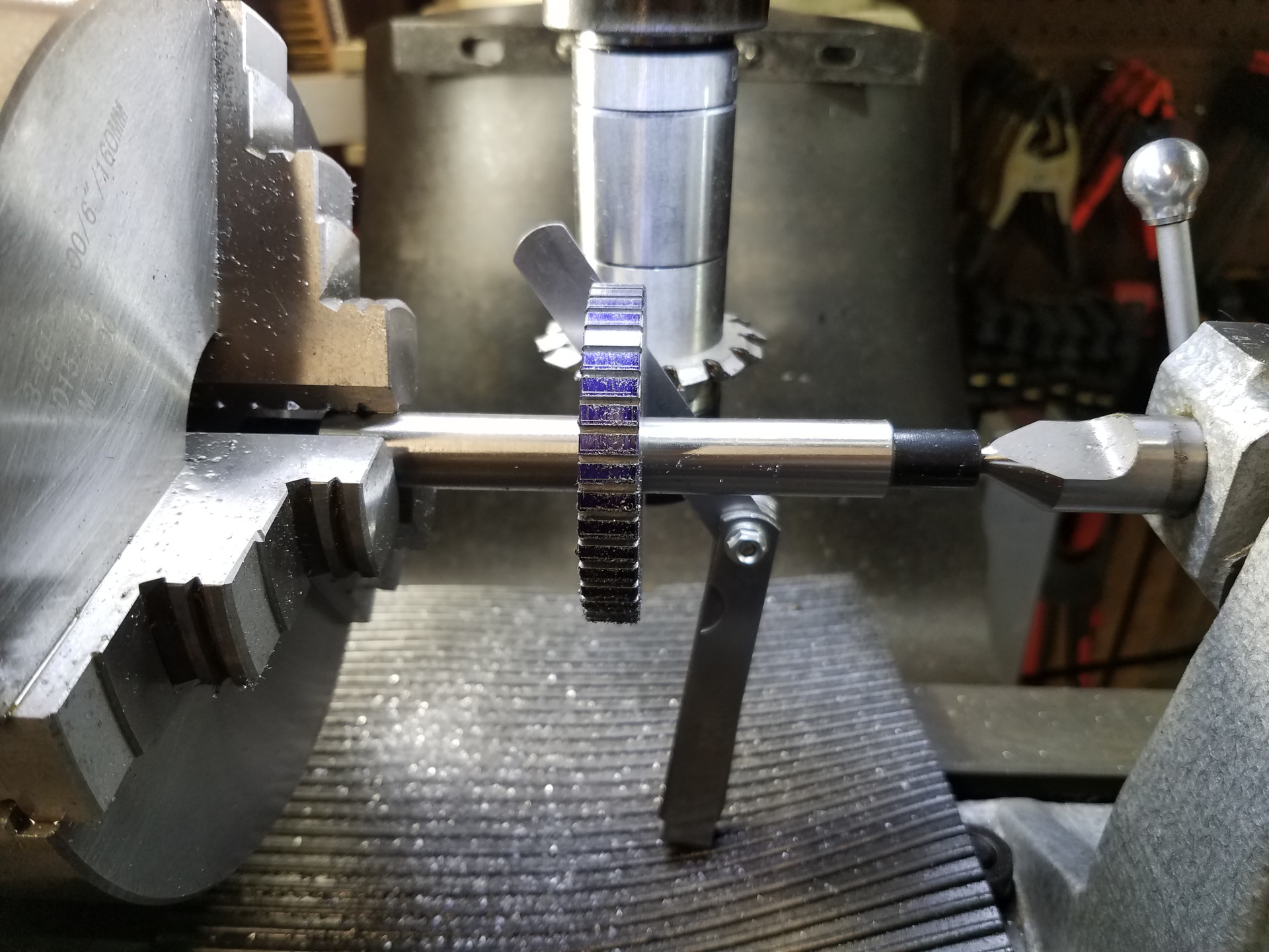
Here all the gear teeth have been cut with one pass of the involute cutter. A lengthy deburring session is next.
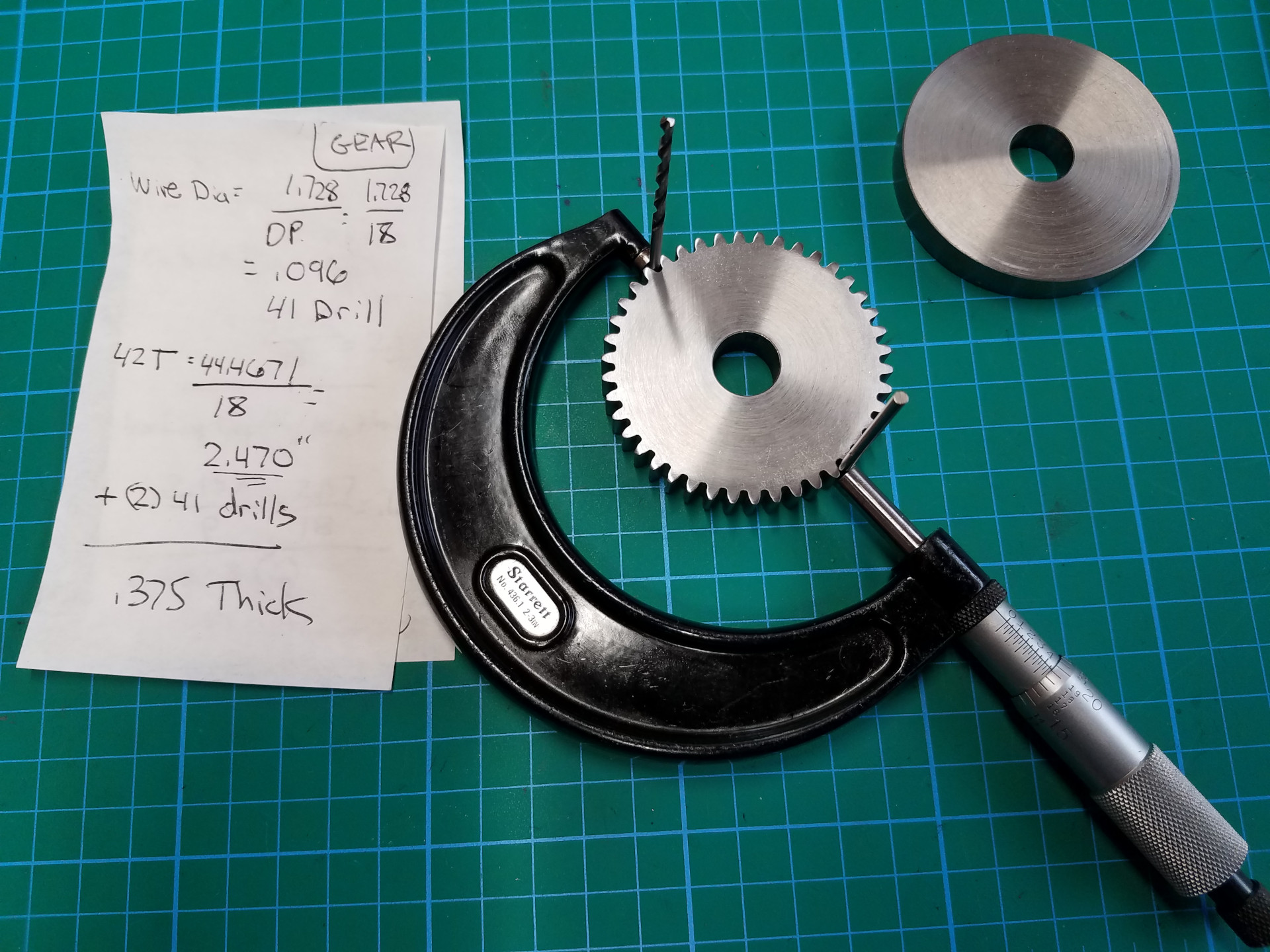
The gear is measured with the two pin method. The web page below has an excellent overview of this procedure and a handy calculator that does the math providing the desired measurement over the two pins.
https://evolventdesign.com/pages/gear-measurement-over-pins-calculator
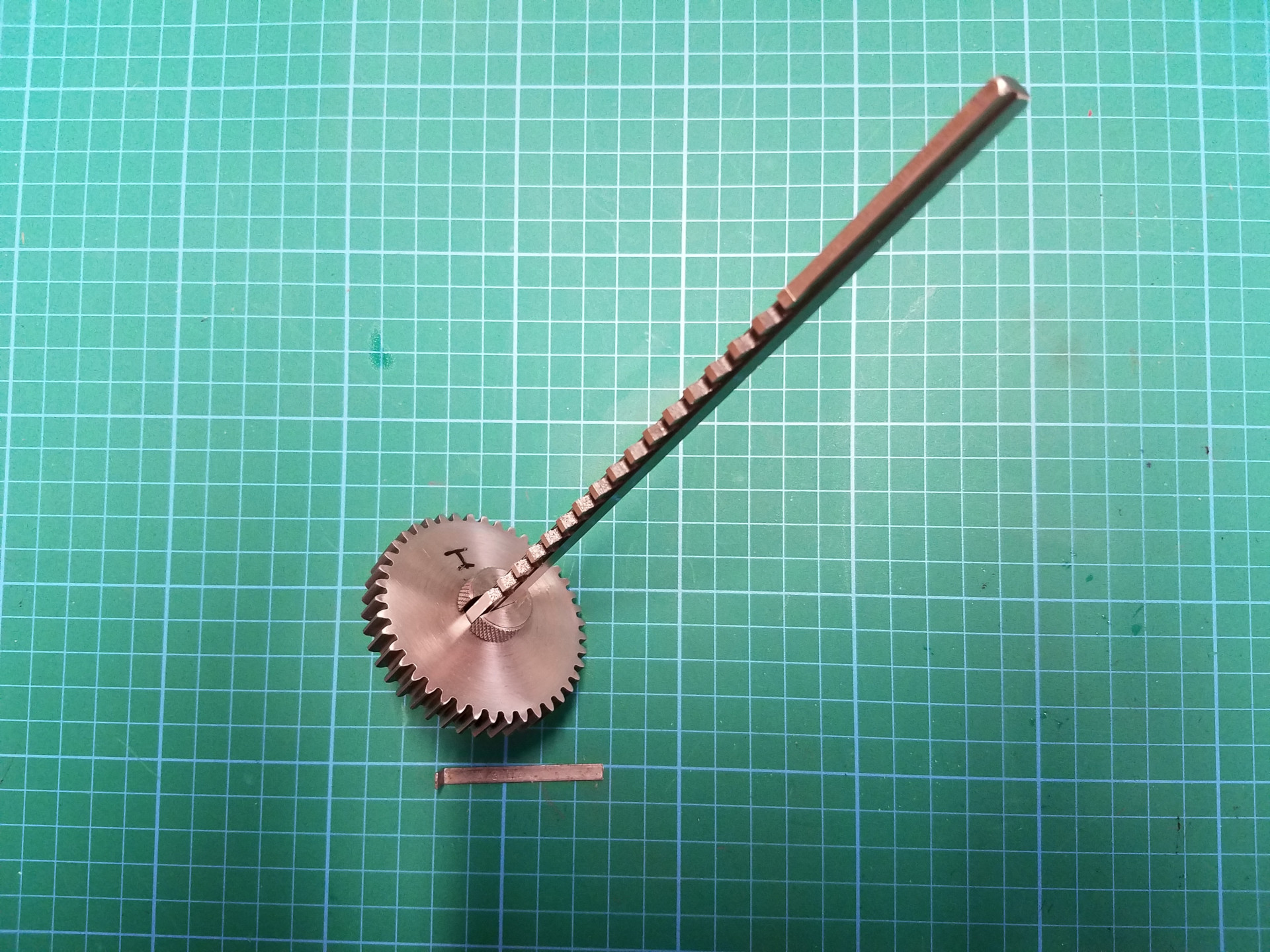
Now that the gear has passed QC, it's time to cut a keyway into the gear. After an arbor bushing was made to fit the hole, the correct broach is fitted into the bushing.
The little Dake press was too small for this operation so the hydraulic press was used to press the broach into the gear. No pictures of that as it's poor lighting at that press. Here the keyway broach operation was completed, with the broach pushed through the gear twice. The 2nd time a shim is used to get the correct keyway depth.
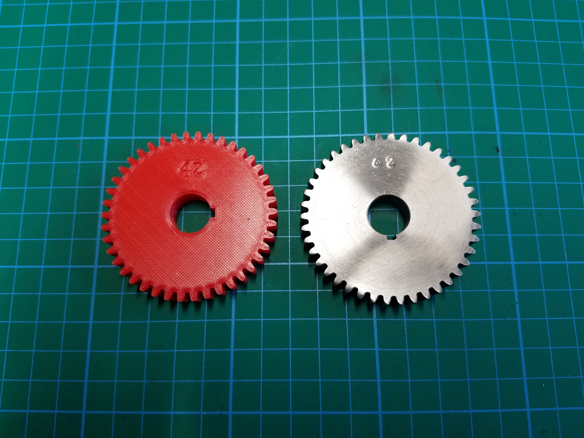
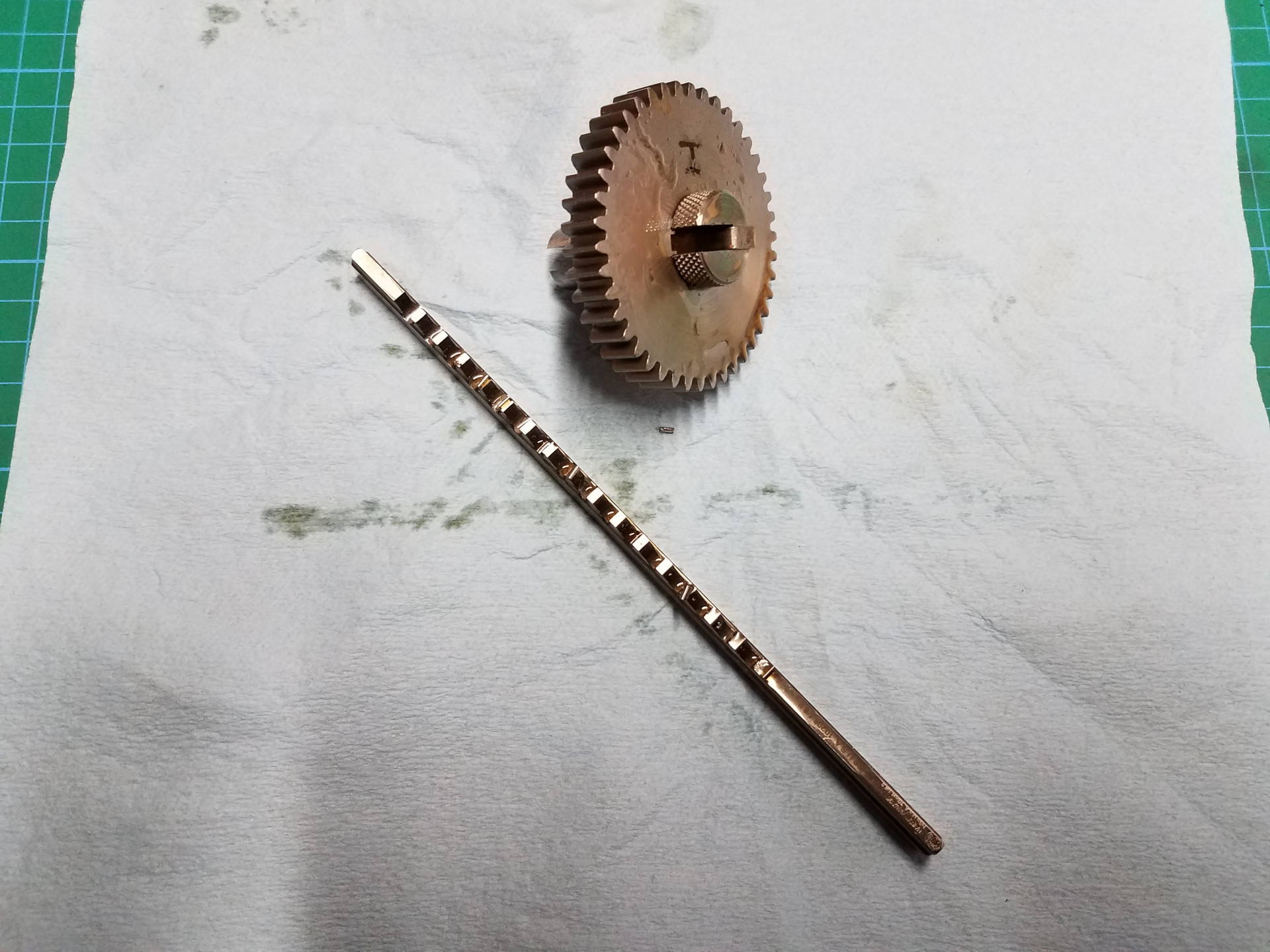
The completed steel gear beside a 3D printed gear. One of these gears was much quicker to make, any guesses?
The main point of this exercise was to streamline the shop procedures for cutting a metal gear and that went quite well. If you only want change gears for a lathe, say a metric transposing set, it's worth exploring the world of 3D printing as the printed gears are perfectly fine for occasional use and perhaps will survive continual use as well. The plastic gear only took a few hours to print.